



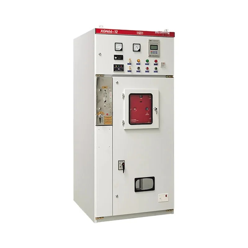
Product Overview
The XGN66-12 fixed enclosed switchgear (hereinafter referred to as the switchgear) is a new complete high-voltage electrical product of our company. It complies with the national standard GB3906 "3-35 kV AC metal-enclosed switchgear", the Ministry of Power standard DLT404 "Ordering technical conditions for indoor AC high-voltage switchgear", and also meets the international standard IEC60298 "Requirements for AC metal-enclosed switchgear and controlgear for rated voltages above 1 kV and up to 52 kV".
Absorbing foreign professional technology, the product is small in volume, only 50% of the volume of an ordinary switchgear cabinet; the circuit breaker features high reliability and good performance, and the "five-prevention" interlock mechanism is reliable and simple. The switchgear is an indoor complete device of 3.6, 7.2 and 12 kV three-phase AC 50 Hz single-busbar sectionalized type, used for receiving and distributing electric energy. It also controls, protects and monitors the circuit; it can be used in various power plants, substations, industrial & mining enterprises and high-rise buildings, and can also be combined with ring main units in switching stations.
Type Designation

Service Conditions
- Altitude not exceeding 1000 m.
- Ambient temperature: -25℃ to +40℃, 24-h average not exceeding +35℃.
- Horizontal inclination not more than 3 degrees.
- Seismic intensity not exceeding degree 8.
- Places without violent vibration, shock or explosion hazards.
Structural Features
- The cabinet is welded from high-quality angle steel.
- The circuit-breaker room is located in the middle (lower) part of the cabinet, convenient for installation, commissioning and maintenance. A VS1 circuit breaker is standard, with a pressure-release channel to ensure personal safety.
- A professional and reliable rotary disconnector is adopted, allowing safe entry into the circuit-breaker room for maintenance while the main busbar is live.
- Whole-cabinet protection class IP2X.
- A reliable and fully functional mandatory mechanical locking device is provided, simply and effectively meeting the "five-prevention" requirements.
- It has a reliable earthing system.
- The door is fitted with an observation window for a clear view of the working state of the components inside.
- The mechanism lock adopts the JSXGN locking mechanism used in XGN2-12 cabinets, simple, reliable, convenient and practical.
- The incoming/outgoing cables are below the front part of the cabinet, convenient for user connection.
The XGN66-12 fixed enclosed switchgear is only 50% of the volume of an ordinary switchgear, especially suitable for distribution sites with limited space.
Main Technical Parameters of the Vacuum Circuit Breaker
Main technical parameters of the switchgear & component models
| No. | Item | Unit | Technical parameters |
|---|---|---|---|
| 1 | Rated voltage | kV | 3.6, 7.2, 12 |
| 2 | Rated power-frequency withstand voltage | kV | to earth & between phases: 42; break: 48 |
| 3 | Rated lightning impulse withstand voltage | kV | to earth, between phases: 75; break: 85 |
| 4 | Rated frequency | Hz | 50 |
| 5 | Rated current | A | 630, 1250 |
| 6 | Rated short-circuit breaking current (r.m.s.) | kA | 20, 25, 31.5 |
| 7 | Rated short-circuit making current (peak) | kA | 50, 63, 80 |
| 8 | Rated dynamic current (peak) | kA | 50, 63, 80 |
| 9 | Rated thermal current 4 s (r.m.s.) | kA | 20, 25, 31.5 |
| 10 | Protection class | - | IP2X |
| 11 | Outline dimensions (W × D × H) | mm | 900×1000×23000 |
| 12 | Weight | kg | approx. 600 |
Main technical parameters of the QCE1-12 vacuum circuit breaker
| No. | Item | Unit | Technical parameters |
|---|---|---|---|
| 1 | Rated voltage | kV | 12 |
| 2 | Rated current | A | 630 1250 |
| 3 | Rated short-circuit breaking current | kA | 20, 25, 31.5 |
| 4 | Rated short-circuit making current | kA | 50, 63, 80 |
| 5 | Rated short-time withstand current (4 s, r.m.s.) | kA | 20, 25, 31.5 |
| 6 | Rated peak withstand current (peak) | kA | 50, 63, 80 |
| 7 | Mechanical endurance | operations | 10000 |
| 8 | Rated short-circuit breaking current breaking operations | operations | 50 |
| 9 | Rated operating sequence | - | O-0.3s-CO-180s-CO |
| 10 | Contact gap | mm | 11±1 |
| 11 | Contact overtravel | mm | 4±0.5 |
| 12 | Phase-to-phase center distance | mm | 210 |
| 13 | Opening speed | m/s | 1.2±0.2 |
| 14 | Closing speed | m/s | 0.6±0.2 |
| 15 | Opening time | ms | ≤ 60 |
| 16 | Closing time | ms | ≤ 75 |
| 17 | Three-phase opening synchronism | ms | ≤ 2 |
| 18 | Closing bounce | ms | ≤ 2 |
| 19 | Circuit resistance | μΩ | ≤ 45 |
| 20 | Cumulative allowable contact wear thickness | mm | 3 |
◇ For technical parameters of other electrical components, see their respective operating manuals.
◇ Schemes with switchgear rated current above 1600 A shall be settled through consultation with our company.
Installation
Refer to the figure below for the installation foundation: the foundation channel steel protrudes 1-3 mm above the ground, the unevenness per meter shall not exceed 1.5 mm, and that over the full length shall not exceed 5 mm.
Place the switchgear on the foundation in order and adjust the installation position, then fix it with M12 bolts or spot welding; tighten cabinets to each other with M8 bolts.
Remove the rear cover plate to install the main busbar and primary cables; the terminal contact surfaces shall be cleaned and coated with neutral vaseline. After installation, seal the primary cable holes.
Connect the earthing busbars between cabinets to form one body along the arrangement direction of the switchgear; check whether the working earthing and protective earthing are complete and whether the earthing circuits are continuously conductive; the working earthing resistance shall not exceed 1000 μΩ and the protective earthing resistance shall not exceed 4 Ω.
Install the secondary cables: the cables enter from the front bottom of the cabinet, go along the side wall into the LV room and are tapped onto the terminal strips; or they are introduced into the LV room from the secondary small busbars on the cabinet top; seal the cable holes after installation.
Clean the dust and debris inside the cabinet.

Commissioning
Before commissioning, the following checks and commissioning tests shall be performed:
- Check whether the models and specifications of the electrical components installed in the cabinet conform to the ordering requirements; check whether fasteners are loose; check whether the primary and secondary wiring is correct; operate the disconnector, earthing switch, circuit breaker and mechanical interlock 3~5 times, which shall be flexible without jamming and the interlock shall meet the "five-prevention" requirements; then apply grease to the moving mechanical parts.
- Check the insulation level and circuit resistance of the switchgear and the mechanical characteristics of the circuit breaker according to Article 3 of this manual and the factory test report; the test results shall be consistent with or close to the factory test report.
Maintenance & Overhaul
Users shall maintain and overhaul the switchgear regularly, including:
- Clean the dust in all parts, especially the accumulated dust on the surfaces of insulating parts;
- Check the moving mechanical parts and add grease regularly to keep their action flexible and reliable;
- Maintain the circuit breaker, disconnector, earthing switch and other components according to their respective manuals;
- Check whether the electrical contact parts are in good condition, whether there is overheating, and whether the earthing circuit is conductive;
- Check regularly whether the fasteners are tightened.
Users should generally carry out fault repair with the assistance of the manufacturer; for minor adjustments and small faults, users may repair by themselves with reference to this manual and the manuals of the main components. Regular maintenance and overhaul per the regulations can effectively extend the service life of the XGN66-12 fixed enclosed switchgear.

Related Products
High-voltage switchgear of the same series and other types available:
- KYN61-40.5(Z) Metal-clad Draw-out AC Metal-enclosed Switchgear
- KYN28A-12 Metal-clad Draw-out Enclosed Switchgear
- XGN15-12 Box-type Fixed AC Metal-enclosed Switchgear
- HXGN-12 Box-type Fixed AC Metal-enclosed Switchgear
- HXGN17-12 Box-type Fixed AC Metal-enclosed Switchgear
- SRM-12 Fully Enclosed Fully Insulated Gas-insulated Ring Main Unit