



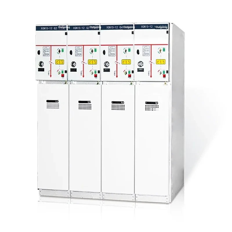
Product Overview
The XGN15-12 unit-type AC metal-enclosed ring-main switchgear (hereinafter referred to as the RMU) is a new high-voltage electrical product designed and developed by us after introducing excellent foreign technology and according to the requirements of rural and urban network renovation in China. All technical performance indicators fully comply with IEC62271-200:2003 and GB3906.
The main switch, operating mechanism and components of the RMU adopt original ABB parts, or SFL-12/24 switchgear produced by domestic assembly of imported parts; ABB original HAD/US type SF6 circuit breakers or VD4-S vacuum circuit breakers can also be equipped per user needs. The operating modes are manual and motorized.
The cabinet is riveted after machining by CNC machine tools, with protection class up to IP3X, reliable mechanical interlock and anti-misoperation functions. The product features small volume, light weight, elegant appearance, easy operation, long life, high parameters, no pollution and low maintenance.
The XGN15-12 unit-type AC metal-enclosed ring-main switchgear is suitable for 50 Hz, 12 kV power networks for receiving and distributing electric energy. The main switch in the cabinet is an SF6 switch.
Type Designation

Main Technical Parameters of the Vacuum Circuit Breaker
| No. | Item | Unit | Value |
|---|---|---|---|
| 1 | Rated voltage | kV | 12 |
| 2 | Rated frequency | Hz | 50 |
| 3 | Rated main busbar current / max. fuse rated current | A | 630,125 |
| 4 | Rated short-time withstand current of main & earthing circuits | kA/s | 20,3 |
| 5 | Rated peak withstand current of main & earthing circuits | kA | 50 |
| 6 | Rated short-circuit making current of main & earthing circuits | kA | 50 |
| 7 | Number of full-capacity breaking operations of the load switch | operations | 100 |
| 8 | Fuse breaking current | kA | 31.5,40 |
| 9 | Rated closed-loop breaking current | A | 630 |
| 10 | Rated transfer current | A | 1600 |
| 11 | Mechanical endurance | operations | 2000 |
| 12 | 1-min power-frequency withstand voltage (peak) phase-to-phase, to earth / isolating gap | kV | 42,48 |
| 13 | Lightning impulse withstand voltage (peak) between phases, to earth / isolating gap | kV | 75,85 |
| 14 | Secondary circuit 1-min power-frequency withstand voltage | kV | 2 |
| 15 | Protection class | - | IP3X |
Structural Features
Cabinet structure
- The RMU cabinet is riveted from 2 mm thick aluminum-zinc-coated sheet (or plastic-sprayed cold-rolled sheet); two pressure-release holes are provided at the rear of the cabinet, one for the cable compartment and the other for the load switch / busbar compartment. This structure can protect personal safety and equipment reliability to the greatest extent.
Compartments
Busbar compartment
The busbar compartment is located at the top of the cabinet and connects adjacent switchgear.
Load switch
The load switch is an independent unit filled with SF6 gas inside.
Cable compartment
About 75% of the space is for cable connection, fuses, earthing switch and CT/PT installation.
Mechanism compartment & interlocks
The compartment contains the operating mechanism and mechanism interlocks as well as position indication, auxiliary contacts, shunt trip coil, live-line indicator and interlocks.
Relay box
The relay box is on the top of the cabinet and is optional. The compartment is used to install special devices such as meters, relays and motor units.
Circuit-breaker compartment
A circuit breaker (SF6 or vacuum) can be placed below the load switch.
Pressure release
Upper pressure release
The upper one releases the gas pressure generated by internal arc accidents in the busbar and load-switch compartments.
Lower pressure release
The lower one releases the gas pressure generated by internal arc accidents in the cable compartment.
SFL load switch (original ABB)
The SFL load switch has double breaking points and rotary moving contacts, using SF6 gas as the arc-extinguishing medium; the moving and fixed contacts are placed in a die-cast epoxy resin housing of reinforced structure. At the operating shaft outlet there is a transparent thermoformed plastic end cap, through which the status can be observed.
Each switch is permanently sealed after being filled with SF6 gas at 1.4 bar (SFL means "permanently sealed"); helium detectors can check for gas leakage.
The switch can be installed vertically or horizontally; in unit-type cabinets, the typical installation is a steel partition between the cable compartment and the busbar compartment with horizontal installation.
This installation seals the switch housing inside earthed steel plates and isolates the busbar from the cable connectors to meet the strictest safety requirements of operation and maintenance.
If internal arcing occurs, there is a structural weak point at the rear of the housing which will burst open, leading the arc gases out of the switch; then the arc-release flap on the top of the cabinet is burst open, guiding the overpressure gas out of the cabinet. The well-designed pressure release enables the XGN15-12 unit-type AC metal-enclosed ring-main switchgear to protect operators and adjacent equipment even under internal fault conditions.

Internal Arc Handling
If internal arcing occurs, there is a structural weak point at the rear of the housing which will burst open, leading the arc gases out of the switch; then the arc-release flap on the top of the cabinet is burst open, guiding the overpressure gas out of the cabinet.
Optional Equipment
- Auxiliary contacts 2 NC 2 NO + extension 2 NO 2 NC
- — Shunt trip coil for SFL with A mechanism.
- Switch with K mechanism: SFL12/17.5 IVDP575305RI, SFL24K IVDP575304RI
- Switch with A mechanism: SFL12/17.5 IVDP575303RI, SFL24A IVDP575302RI
VD4-S Vacuum Circuit Breaker (original ABB)
The VD4-S vacuum circuit breaker is designed specially for unit switchgear; its breaking capacity is sufficient for all conditions, including normal switching of equipment or branch networks and short-circuit breaking under special circumstances. The vacuum circuit breaker is especially suitable for networks with frequent operations within the working current range. The VD4-S vacuum circuit breaker is fitted with a spring operating mechanism with auto-reclosing function (O-0.3s-CO-180s-CO), reliable action and long life. The whole breaker includes three vacuum interrupters with a resin-insulated cylinder outside, in vertical structure.
Arc extinction results from the forced displacement of the arc by the spiral grooves of the arcing contacts. Since the minimum static vacuum inside the switch insulation cylinder is 10-4 to 10-8 bar, a very high insulation strength is obtained even though the gap between the switch contacts is relatively small. The arc extinguishes at the first zero point of the short-circuit current.
Owing to the small contact gap, the high conductivity of the metal-vapor plasma region at the arc voltage drop, and the short arcing time, the arc energy is extremely low, which is beneficial to extending the life of the contacts and the whole switch.
Standard Equipment
- Manual operation
- Motorized operation
- Auxiliary contacts 2 NO 2 NC
- Shunt trip with position contacts
- Shunt closing coil
Optional Equipment
- S5 or PR512 over-current relay
- Undervoltage release
- Interlocking coil
Circuit Breaker Models
- VD41206-20S
- VD41706
- VD42406
HAD/US SF6 Circuit Breaker (original ABB)
The HAD/US SF6 circuit breaker is designed specially for ring-main switchgear; its breaking capacity is sufficient for all conditions, including normal switching of equipment or branch networks and short-circuit breaking under special circumstances. The new HAD has a new SF6 breaking process and a simple structure requiring only a small operating energy; such a simple energy-storage operating mechanism features long mechanical life in use. The breaker with a spring operating mechanism can realize auto-reclosing. The special structure of the breaking part provides extraordinary assurance of extended electrical life. The switch is made as a split independent post-type structure, placed vertically. The switch adopts the self-energy arc-blowing principle, i.e. using the arc's own energy to extinguish the arc. When the breaker opens, an arc is generated between the moving and fixed contacts in the interrupter; the high temperature and strong ionization cause the SF6 gas pressure to rise rapidly in the interrupter, and with the pressure building up and the arcing contacts gradually separating, the gas is forced through the nozzle to outside the interrupter, making the arc thin, cooled and interrupted and preventing re-ignition. Therefore the moving parts of the switch need very little energy, further enhancing long-term operational reliability.

SFL Technical Data
| Rated voltage | kV | 12 | 17.5 | 24 |
|---|---|---|---|---|
| Impulse withstand voltage | kV | 75 | 95 | 125 |
| 1-min power-frequency withstand voltage | kV | 28 | 38 | 50 |
| Rated current | A | 630 | 630 | 630 |
| Making capacity | kA | 50 | 50 | 40 |
| Thermal current | kA/s | 20,3 | - | - |
| Breaking capacity | A | 1700 | - | - |
| Max. fuse | A | 125 | - | - |
| Pole distance | mm | 210 | 210 | 210 |
VD4-S Technical Data
| Rated voltage | kV | 12 | 17.5 | 24 |
|---|---|---|---|---|
| Impulse withstand voltage | kV | 75 | 95 | 125 |
| Power-frequency withstand voltage | kV | 28 | 38 | 50 |
| Rated current | A | 630 | 630 | 630 |
| Thermal current | kA/s | 20,3 | - | - |
| Pole distance | mm | 210 | 210 | 210 |
This switch has many advantages:
- Short arcing duration; the insulation strength in the interrupter recovers rapidly.
- Safe and reliable even in the most severe environments.
- Capable of breaking low-value inductive and capacitive currents.
- Simple operating mechanism, fast open/close, long mechanical life.
- Reduced wear of contacts and arc chamber, i.e. extended electrical life.
- Many permitted operations with very little maintenance.
- Light, compact and stable structure.
Standard equipment
- Motorized operation
- Manual operation
- Auxiliary contacts (2 NO 2 NC)
- Shunt trip with position contacts
- Shunt closing coil
- Gas pressure control of signal contacts
Optional equipment - S5 solid over-current relay
- PR511 - PR512 over-current relay
- Undervoltage release
- Interlocking coil
- HAD120625
- HAD120520
- HAD170620
- HAD170616

Type K & A Operating Mechanisms (original ABB)
This mechanism is used to operate load switches and load switches with fuses.
Type K mechanism
The type K mechanism is a single-spring mechanism for closing/opening the load switch; the closing/opening is realized through spring energy via the dead point. A motor can be selected for the type K mechanism to achieve motorized operation.
Type A mechanism
The type A mechanism is a double-spring mechanism, one spring for closing and the other for opening. Before the switch is closed by the closing spring, it must be in the energy-storage state; after the closing operation the opening spring is automatically placed in the energy-storage state. Tripping can then be performed manually, by a shunt trip coil or by a fuse striker.
Mechanism models
- For load switches
- K mechanism 1VDP586042R1
- For load switches with fuses
- A mechanism 1VDP575013R1
Optional equipment
- Motorized operation on the K mechanism
| Operating voltage kV | Transformer rated capacity | |||||||||||||||
|---|---|---|---|---|---|---|---|---|---|---|---|---|---|---|---|---|
| 50 | 75 | 100 | 125 | 160 | 200 | 250 | 315 | 400 | 500 | 630 | 800 | 1000 | 1250 | 1600 | 2000 | |
| Fuse selection (nominal values in amperes) | ||||||||||||||||
| 3 | 25 | 25 | 40 | 40 | 63 | 63 | 63 | 80 | 100 | 100 | 160 | - | - | - | - | - |
| 5 | 16 | 16 | 25 | 25 | 40 | 40 | 63 | 63 | 63 | 80 | 100 | 100 | 160 | - | - | - |
| 6 | 16 | 10 | 25 | 25 | 25 | 40 | 40 | 63 | 63 | 63 | 80 | 100 | 100 | 160 | - | - |
| 10 | 10 | 10 | 16 | 16 | 25 | 25 | 25 | 40 | 40 | 63 | 63 | 63 | 80 | 100 | 100 | - |
| 12 | 10 | 10 | 16 | 16 | 16 | 25 | 25 | 40 | 40 | 63 | 63 | 63 | 80 | 100 | - | - |
| 15 | 10 | 10 | 16 | 16 | 16 | 16 | 25 | 25 | 25 | 40 | 40 | 63 | 63 | 63 | 100 | - |
| 20 | 10 | 10 | 10 | 10 | 16 | 16 | 16 | 25 | 25 | 25 | 40 | 40 | 63 | 63 | -63 | 80 |
| 24 | 10 | 10 | 10 | 10 | 16 | 16 | 16 | 15 | 25 | 25 | 25 | 40 | 40 | 63 | 63 | 63 |
SFL-12/24 Switchgear
The main components of the SFL12/24 switchgear are imported original parts. The switchgear has double breaking points, three positions and rotary moving contacts, using SF6 gas as the arc-extinguishing medium; the moving contacts are placed in a die-cast epoxy resin housing of reinforced structure.
Each switch is permanently sealed after being filled with SF6 gas at 0.4 bar; helium detectors can check for gas leakage. The switch can be installed vertically or horizontally; in the RMU the typical installation is a steel plate between the cable compartment and the busbar compartment with horizontal installation, which isolates the busbar from the cable connectors to meet the strictest safety requirements of operation and maintenance. If internal arcing occurs, there is a structural weak point at the rear of the housing which will burst open; then the arc-release flap on the top of the cabinet opens and guides the overpressure flow out of the cabinet. Optional equipment — auxiliary contacts 2 NC 2 NO + extension 2 NO 2 NC — shunt trip coil for SFL with A mechanism.
| Rated voltage | Unit | 12 | 17.5 | 24 |
|---|---|---|---|---|
| Impulse withstand voltage | kV | 75 | 95 | 125 |
| 1-min power-frequency withstand voltage | - | 42 | 55 | 65 |
| Rated current | A | 630 | 630 | 630 |
| Making capacity | kA | 50 | 50 | 40 |
| Thermal current | kA/s | 20/3 | - | - |
| Breaking capacity | A | 1700 | - | - |
| Max. fuse | A | 125 | - | - |
| Pole distance | mm | 210 | 210 | 210 |
Operating Mechanism
Dual-function mechanism: type K - switch function
Independent closing/opening operations by operating lever or motor.
Auxiliary contacts: —— switch (20+2C)/switch (20+3C) and earthing switch (10+1C)
Earthing-switch function
Independent closing/opening operations by operating lever; the operating energy is provided by a compressed spring, which, when released, closes or opens the contacts rapidly.
Mechanical indication: —— mechanical indicator when the fuse in the assembly melts / motor option / AC 220 V/DC 220 V
Dual-function operating mechanism: type A - switch function
Independent closing/opening operations by operating lever or motor; the operating energy is provided by a compressed spring which, when released, closes the contacts. Independent opening/closing operations by button (O) or tripping unit.
Earthing-switch function
Independent closing/opening operations by operating lever; the operating energy is provided by a compressed spring which, when released, closes or opens the contacts rapidly.
Auxiliary contacts: —— switch (20+2C) and earthing switch (10+1C)/switch with motor option (1C) and earthing switch /(10+1C) / fuse blown (1C)/mechanical indication / tripping / shunt trip / undervoltage / motor option
Interlocks
The switchgear has the following interlocks:
- When the load switch is in the closed position, the earthing switch operation is locked;
- When the earthing switch is in the closed position, the load switch operation is locked;
- Only when the earthing switch is closed may the front door of the RMU be opened; in other cases the front door is locked.
Operation
For switchgear with a load switch, operate on the front of the switchgear with a special operating handle; the front of the operating mechanism has two operating holes, the upper for the earthing switch and the lower for the load switch. During operation, rotating the handle clockwise closes the switch and counterclockwise opens it. Motorized opening/closing devices can also be added for remote operation. (Note: sometimes the load switch has no earthing switch, and the earthing-switch operating hole is used for unlocking the cabinet door.)
For switchgear with combination apparatus, except that the load switch is opened by a manual opening button, the others are the same as the above operating sequence. The combination apparatus cabinet has an additional lower earthing switch linked with the upper earthing switch to open and close simultaneously, releasing the residual small current on the lower fuse seat when closing, so as to improve safety when replacing fuses.
Outline Dimensions
The interlock and operation design of the XGN15-12 unit-type AC metal-enclosed ring-main switchgear prevents misoperation and facilitates daily maintenance by operating personnel.

Technical Parameters
| No. | Item | Unit | Value |
|---|---|---|---|
| 1 | Circuit-breaker cabinet width | mm | 750 |
| 2 | Other cabinet widths | mm | 375,500 |
| 3 | Height | mm | 1600,1850 |
| 4 | Depth | mm | 980,900 |
| 5 | Relay box height | mm | 450 |
Technical Scheme Illustrations
| Scheme No. | 01 | 01-1 | 01-2 | 01-3 |
|---|---|---|---|---|
| Primary circuit diagram |  |
|||
| Application | Incoming/outgoing | Incoming/outgoing | Incoming/outgoing | Incoming/outgoing (right or left) |
| Load switch FLN36-12D | 1 | 1 | 1 | 1 |
| Fuse | 1 | 1 | 1 | 1 |
| Current transformer LZZJ-12 | - | 1~3 | - | - |
| HV live-line display device DXN6-T | 1 | 1 | 1 | 1 |
| Surge arrester HY5WZ or HY5WS | - | - | 3 | - |
| W × D × H (mm) | 420/500x845x1600/1800 | |||
| Scheme No. | 02 | 02-1 | 02-2 |
|---|---|---|---|
| Primary circuit diagram |  |
||
| Application | Transformer protection | Transformer protection | Transformer protection |
| Combination apparatus FLN36-12D | 1 | 1 | 1 |
| Fuse | S □ LAJ | S □ LAJ | S □ LAJ |
| Current transformer LZZJ-12 | - | 1~3 | - |
| HV live-line display device DXN6-T | 1 | 1 | 1 |
| Surge arrester | - | - | HY5WZ |
| Earthing switch | 1 | 1 | 1 |
| W × D × H (mm) | 500x845x1600/1800 | 500x845x1600/1800 | 500x845x1600/1800 |
Related Products
High-voltage switchgear of the same series and other types available:
- KYN61-40.5(Z) Metal-clad Draw-out AC Metal-enclosed Switchgear
- KYN28A-12 Metal-clad Draw-out Enclosed Switchgear
- XGN66-12(Z) Fixed Enclosed Switchgear
- HXGN-12 Box-type Fixed AC Metal-enclosed Switchgear
- HXGN17-12 Box-type Fixed AC Metal-enclosed Switchgear
- SRM-12 Fully Enclosed Fully Insulated Gas-insulated Ring Main Unit