



Product Overview
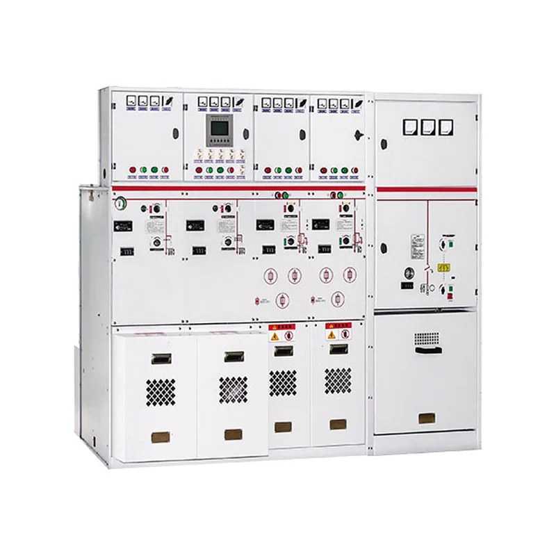
The SRM□-12 series ring-main switchgear is SF6 gas-insulated metal common-tank enclosed switchgear, which can be composed of modules of load-switch units, load-switch fuse combination units, vacuum circuit-breaker units and busbar incoming units. Adopting a series of excellent technologies and materials, it has excellent electrical and mechanical properties, is little affected by environment and climate, is compact, easy to install, convenient to operate, maintenance-free, and has flexible combination modes. The clear and intuitive design ensures simple and direct operation. The feeder connection capacity is large, suitable for various connection systems. The SRM□-12 series ring-main switchgear is SF6 gas-insulated metal common-tank enclosed switchgear, compact, easy to install, and can operate for a long time without maintenance.
Unit Definitions
| Unit code | Meaning |
|---|---|
| C | Standard single-bushing load-switch unit |
| F | Load switch-fuse combination unit |
| V | Circuit-breaker unit |
| D | Cable incoming unit (without switch) |
| + | Busbar-side bushing |
| - | Busbar-top bushing |
| SL | Bus-tie unit |
| M | Metering unit |
| PT | PT unit |
| 1K2(4) | Load-switch unit with double-bushing outgoing |
Product Features
Operational safety:
Through the following safety measures, we can provide users with special safety guarantees:
- Integrated three-position load switch
- The load switch replaces the disconnector for the circuit breaker, safer and more reliable; the fully sealed primary-side design protects against accidental contact; the mechanical interlock meeting the five-prevention requirements; the live-line indicator can provide incoming
- and outgoing live indication. Reliable operation: fully sealed design; all 10 kV switches and live busbar parts are sealed in a gas tank welded from 3 mm stainless steel plates; with silicone-rubber cable plugs,
- realizing fully insulated and fully sealed cable heads, unaffected by dust, moisture, small animals and other external influences. The spring energy-storage operating mechanism can be operated manually or motorized; the panel mimic diagram provides the switch
- position indication. The cabinet is made of galvanized sheet with electrostatic spraying, enhancing corrosion resistance; the pressure gauge monitors the SF6 gas safety pressure range in the tank.
Economy:
- Maintenance-free
- Highly reliable
- Service life up to 20 years
Flexible schemes:
- Various incoming modes: left, right, top or front incoming
- Various combination modes: any combination between units
- With insulated busbars, cabinets can be joined front-rear or left-right
- Flexible design schemes
Wide application:
Large feeder capacity and small footprint, suitable for various application needs. Whether terminal supply or ring-main supply, the SRM□-12 series ring-main switchgear can meet configuration requirements with flexible module combinations.
Performance Indicators
| SF6 gas pressure | 1.4 bar absolute pressure at 20℃ | Normal service conditions | |
| Annual gas leakage rate | 0.2% per year | Max. temperature | 40℃ |
| Protection class | IP67 | Min. temperature | -40℃ |
| Stainless steel thickness of gas tank | 3.0mm | Max. average relative humidity | ≤ 95% |
| Busbar | - | Altitude | ≤2000 m |
| Busbar inside switchgear | 400mm²Cu | Complying with standards | |
| Earthing busbar of switchgear | 150mm²Cu | GB/T11022 GB16926 GB3309 GB3906 GB38041 GB160129 GB1985 GB1984 GB60265 GB60420 GB60694 |
|
| Color | - | - | - |
| Front panel of switchgear | RAL7012 | - | - |
| Side plates & front cover plate of cable compartment | RAL7035 | - | - |
Auxiliary Equipment Parameters
| Item | C module | F module | V module | CB module | ||||
| Load switch | Combination apparatus | Vacuum switch | Isolating / earthing switch | Vacuum circuit breaker | Isolating / earthing switch | |||
| Rated voltage kV | 12 | 12 | 12 | 12 | 12 | 12 | ||
| Rated frequency Hz | 50 | 50 | 50 | 50 | 50 | 50 | ||
| Power-frequency withstand voltage (between phases / break) kV | 42/48 | 42/48 | 42/48 | 42/48 | 42/48 | 42/48 | ||
| Lightning impulse withstand voltage kV | 75/85 | 75/85 | 75/85 | 75/85 | 75/85 | 75/85 | ||
| Rated current A | 630 | Note | - | 630 | - | 1250/630 | - | |
| Rated closed-loop breaking current A | 630 | - | - | - | - | - | - | |
| Rated cable-charging breaking current A | 135/135 | - | - | - | - | - | - | |
| Rated short-circuit making current (peak) | 50 | 80 | - | - | - | - | ||
| Rated peak withstand current kA | 50 | - | - | - | - | - | - | |
| Rated short-time withstand current kA/s | 20 | - | - | - | - | - | - | |
| Rated short-circuit breaking current kA | - | - | 31.5 | 20 | - | 25 | 25 | |
| Rated transfer current A | - | - | 1750 | - | - | - | - | |
| Max. current of matched fuse A | - | - | 125 | - | - | - | - | |
| Circuit resistance Ω | ≤ 300 | ≤ 600 | - | - | - | - | ||
| Mechanical endurance (operations) | 5000 | 3000 | 5000 | 2000 | 5000 | 5000 | ||
Note: (1) Depends on the current rating of the fuse.
Design description
SRM□-12 The gas fully-insulated fully-enclosed switchgear is installed on a galvanized sheet frame, with the switch units in the SF6 gas tank made of anti-corrosive, non-magnetic 3 mm thick stainless steel plates.SF6 The gas tank is a "sealed pressure system",It can operate for 20 years under normal working conditions。SF6 The gas pressure in normal operation is 0.015~0.04MPa。The gas tank is fitted with a pressure-release device; when the pressure is too high, gas is released from the bottom or the rear。The pressure-release device further improves the operational safety of the SRM□-12-12 series ring-main switchgear。
Switch unit
The load switch adopts a coaxial rotary double-break design; through the same operating hole and the slide plate, functional operations are performed, so the switch can only be in one of the “closed, open and earthed” three states at any moment, completely avoiding misoperation。

Pressure-release device
The pressure-release device is separated from the cable compartment by a metal plate; if the pressure in the gas tank is too high, the explosion-proof diaphragm in the device ruptures to release the pressure.

Operating Mechanism
The operating mechanism is installed outside the gas tank at the front, specially treated for rust prevention, convenient for manual operation and maintenance, and easily motorized. A spring mechanism or permanent-magnet mechanism can be used.

Cable compartment & connection
The cable connection compartment is spacious, and the bushings are of standard design compatible with all European-standard cable plugs. Normally each load-switch unit can connect 1~3 outgoing circuits, specially designed types 4~6, and the vacuum circuit-breaker unit 1~2.
International-standard universal bushings (complying with DIN47636 or American standard) are used, facilitating selection of corresponding cable accessories. T-type front and rear cable plugs are used with European graduated bolt-tightening structure; the front plug is connected to the bushing with M16 bolts. Ordinary terminals with heat-shrink sleeves are also available as connection method.

Surge arrester connection

The load-switch unit can be fitted with a T-type rear-plug silicone-rubber fully-sealed metal-oxide surge arrester; when there are many cable circuits and space is insufficient, a π-type rear-plug surge arrester can be used.
Fuse
Fuse replacement of the SRM□-12 gas fully-insulated fully-enclosed ring-main switchgear is direct and simple. The fuse is placed in an insulating tube inside the SF6 metal gas tank; this design has the following advantages:
- The fuse cap and sealing device are at the weakest part of the electric field.
- No conductive matter can adhere to the fuse assembly.
- The parts in the SF6 gas are completely protected.
- No additional insulation is needed for the fuse cap. The spring energy-storage operating mechanism and the linked tripping device ensure that the three phases of the load switch open simultaneously and automatically when any phase fuse blows.

SRM□-12 series switch panel indication
① Live-line indicator
② Main switch operating hole (operation order: clockwise to close / counterclockwise to open)
③ Earthing-switch operating hole (operation order: clockwise to close / counterclockwise to open)
④ Open/close position indication (red for closed / white for open)
⑤ Earthing position indication
⑥ Padlock position of the load switch
⑦ Padlock position of the earthing switch
C unit
1. Load-switch unit C
The switch can be classified into single unit, single unit with double bushing outgoing, two-unit, three-unit, four-unit, five-unit standard types and the type with side incoming bushings, adopting a structure sharing one SF6 gas tank; no external busbar connection is needed between units, so the structure is relatively simplified, easy to install and safer; although the gas tank is integral, each unit still has an independent compartment. Six or more units are realized by joining cabinets with insulated busbars, front-rear or left-right, the cabinet being the standard type with busbar bushings on the upper side.
2. Standard configurations
- 630 A busbar
- Three-position load / earthing switch
- Spring operating mechanism
- Position indication of load switch and earthing switch
- Horizontally arranged outgoing bushings at the front
- Incoming / busbar voltage indicator (single or busbar extension type)
- Outgoing voltage indicator
- All switch functions can be controlled by adding padlocks on the panel
- Interlock between the earthing switch and the cable compartment door
- SF6 pressure gauge
- Earthing copper bar
- Explosion-proof pressure-release valve
3. Optional configurations
- Short-circuit & earth fault indicator
- Measuring ring-type current transformer and ammeter
- Metering ring-type current transformer
- Key lock for switch position
- Motorized operating mechanism
- Permanent-magnet operating mechanism
- Reserved busbar extension
- External busbar

Fuse replacement steps:
Rotate half a turn counterclockwise with the operating handle and pull out to replace the fuse; when installing, align the hook position and rotate clockwise。

SRM□-12 Switch panel indication

F unit
1. Combination apparatus unit
The combination apparatus unit is used for transformer protection with capacity up to 1250 kVA; the unit is fitted with an insulating cylinder that can hold the fuse. The insulating cylinder is placed inside the SF6 gas tank, further improving its insulation performance. When closed, the lower side of the fuse is earthed at the same time and the upper side of the fuse is safely isolated from the power supply, ensuring personnel safety when replacing the fuse. To prevent phase-failure operation of electrical equipment after one fuse blows, this unit is fitted with a linked tripping mechanism; when the tripping observation window shows red, the tripping device has actuated or the fuse has melted and tripped. This unit can be combined with other units to realize ring-main supply.
2. Standard configurations
- 630 A busbar
- Three-position load / earthing switch
- Spring operating mechanism
- Position indication of load switch and earthing switch
- Horizontally arranged outgoing bushings at the front
- Incoming / busbar voltage indicator (single or busbar extension type)
- Outgoing voltage indicator
- All switch functions can be controlled by adding padlocks on the panel
- Interlock between the earthing switch and the cable compartment door
- SF6 pressure gauge
- Earthing copper bar
- Explosion-proof pressure-release valve
3. Optional configurations
- Short-circuit & earth fault indicator
- Measuring ring-type current transformer and ammeter
- Metering ring-type current transformer
- Key lock for switch position
- Motorized operating mechanism
- Permanent-magnet operating mechanism
- Reserved busbar extension
- External busbar
SRM□-12-F switch panel indication

SRM□-12-F switch panel indication

V unit
1. Vacuum circuit-breaker unit
A spring-type vacuum circuit breaker is adopted with mechanical life up to 10000 operations (fast protection action, opening time not exceeding 30 ms), easy to achieve graded coordination. A three-position load disconnector is used. The vacuum circuit breaker and the load switch are sealed together in an SF6 gas tank made of 3 mm thick stainless steel plates; the whole system is fully insulated, fully sealed and maintenance-free.
2. Standard configurations
- 630 A busbar
- 630 A circuit-breaker module ISM
- Controller CM (DC 24 V operating power supply)
- Three-position load disconnector
- External supply, self-powered
- Microprocessor protection device
- Bushing-type protection CT
- SF6 pressure gauge
- Bushings complying with DIN47636
- Interlock between earthing switch and cable compartment door
- Auxiliary contacts for VCB position: 2NO+2NC
- Operating power supply (including PT, power module, backup battery)
3. Optional configurations
- Connecting busbar
- Measuring current transformer and ammeter
- Auxiliary contacts: load disconnector position 2NO+2NC, earthing switch position 2NO+2NC
- Permanent-magnet mechanism for fast opening/closing of the breaker, used for boundary circuit-breaker switchgear or incoming switchgear

SRM-12-V switch panel indication
13

SRM-12-V switch panel indication
14

Accessories overview
1. Auxiliary contacts
All load switches and earthing switches can be configured with auxiliary contacts indicating the switch position, installed inside the operating mechanism.
2. Remote control & telemetry unit
The SRM□-12 series fully-insulated fully-enclosed switchgear can be configured with an integrated remote control & monitoring unit; this prefabricated product can be assembled in the factory.
3. Live-line indicator
The incoming/outgoing bushings of the switch unit are fitted with capacitive voltage indicating devices. Each live-line indicator also has three-phase voltage phasing outlet points; a phaser can be configured for phasing.
4. Short-circuit / earth fault indicator
To facilitate fault locating, the switch unit can be configured with a short-circuit / earth fault indicator.
5. Cable connection
The SRM□-12 series fully-insulated fully-enclosed switchgear is configured with DIN47636-type standard bushings. The cable compartment door is interlocked with the earthing switch. Different switch connection units can be selected according to the number of outgoing circuits.
6. Pressure indicating instrument
The SRM□-12 series fully-insulated fully-enclosed switchgear is all equipped with an SF6 gas pressure gauge.
7. Key lock
The SRM□-12 series fully-insulated fully-enclosed switchgear can be configured with key locks for the load switch and earthing switch.
8. Access lock
The SRM□-12 series fully-insulated fully-enclosed switchgear can be configured with padlocks preventing operation by non-authorized personnel.
9. Secondary wiring compartment / metering box
The SRM□-12 series fully-insulated fully-enclosed switchgear can be configured with a secondary wiring compartment / metering box for installing secondary accessories and meters.

Accessories overview
10. Surge arrester
The SRM□-12 series fully-insulated fully-enclosed switchgear can be configured with T-type silicone-rubber plug-in metal-oxide surge arresters.
- Continuous operating voltage 13.6 kV
- U1mA.DC reference voltage ≥25 kV
- 0.75U1mA.DC leakage current ≤50 μA
11. Separable connector
T-type front and rear plugs, PT elbow plug; while completing the cable connection, a π-type plug of a plug-in metal-oxide surge arrester can also be installed.
12. Current transformer
The SRM□-12 series fully-insulated fully-enclosed switchgear can be configured with through-type current transformers as needed for metering / measurement:
- Secondary output 5 A
- Accuracy class 0.2 or 0.5. The circuit-breaker unit adopts a built-in CT:
- Epoxy resin casting
- Moisture-proof design of secondary leads
- Bushing-type installation
13、Voltage transformer
The SRM□-12 series fully-insulated fully-enclosed switchgear can be configured with a 10 kV fully sealed voltage transformer as needed to meet distribution automation requirements, providing voltage signals for metering / measurement and power for the motorized operating mechanism.
- Single / three phase selectable as needed
- Ratio: 10/0.1/0.22 kV
- Accuracy (AC 100 V): class 0.2 or 0.5

Accessories overview
14. Special busbar for cabinet joining
Fully insulated, fully sealed structure.
15. Fuse
Users may configure by themselves per their needs, or our company can recommend and provide the configuration per applicable standards. We recommend HVHRC fuses, which are backup fuses with temperature-protection devices preventing equipment damage caused by abnormal overheating in the fuse cylinder; when ordering, please specify the rated capacity of the transformer, the operating voltage and the rated current of the fuse.
16. Protection relay
A digital self-powered multifunctional time over-current protection relay is adopted: compact design, strong environmental adaptability, complying with standards
VDE0435-303,
IEC60225,
VDE0843。
- No external power supply needed
- Built-in safe protection operation mode
- Wide setting range, simple operation steps
- Microprocessor signal processing for high-precision parameter measurement
- Internal self-check (watchdog) design for reliable operation
- Protection functions selectable
- Definite-time over-current protection (DMT)
- Inverse-time over-current protection (IDMT)
- Inverse-time curves selectable:
- Standard inverse
- Very inverse
- Extremely inverse

Cable compartment & connection that truly meet your needs
Fifteen standard combinations are provided in total.
Each module of the various non-extensible standard combination unit cabinets of SRM□-12 has the following configurations
- D cabinet — riser module
- Standard configuration & features of the "cable connection module without earthing switch"
- C cabinet — load-switch module
- Standard configuration & features of the "load-switch module"
- F cabinet — load-switch fuse combination module
- Standard configuration & features of the "load-switch fuse combination module"
- V cabinet — vacuum switch module
- Standard configuration & features of the "vacuum switch module"
- Capacitive voltage indicator of the incoming bushing
- One pressure gauge monitoring the SF6 density per gas chamber
- Lifting lugs for hoisting
- Operating handle
- Optional
- Motorized operating mechanism
- Cable short-circuit & earth fault indicator
- Current transformer and meters
- Remote monitoring and earth fault indicator

Outline dimensions & weight
The outline dimensions and weight of each unit configuration of the switchgear are as follows:
| Configuration | Weight | Outline dimensions (W×D×H mm) |
|---|---|---|
| Standard 2-way DF | 260 Kg | 650 × 1300 × 2000 |
| Standard 3-way CCC | 300 kg | — |
| Standard 4-way CCCC | 390 kg | 1300 × 1625 × 2000 |
| Standard 3-way CFC | 320 kg | — |
| Standard 4-way CCFF | 430 kg | 1300 × 1625 × 2000 |
| Standard 5-way CCCFF | 520 kg | 1300 × 1825 × 2000 |
| Standard 4-way CFFC | 430 kg | 1300 × 1625 × 2000 |
| Standard 4-way CCVV | 411 kg | — |
| Standard 5-way CCCCF | 500 kg | 1300 × 1825 × 2000 |
Note: outline dimensions are subject to the product drawings; see the annotations in the figures above for specific dimensions。

Related Products
High-voltage switchgear of the same series and other types available:
- KYN61-40.5(Z) Metal-clad Draw-out AC Metal-enclosed Switchgear
- KYN28A-12 Metal-clad Draw-out Enclosed Switchgear
- XGN66-12(Z) Fixed Enclosed Switchgear
- XGN15-12 Box-type Fixed AC Metal-enclosed Switchgear
- HXGN-12 Box-type Fixed AC Metal-enclosed Switchgear
- HXGN17-12 Box-type Fixed AC Metal-enclosed Switchgear