



Product Overview
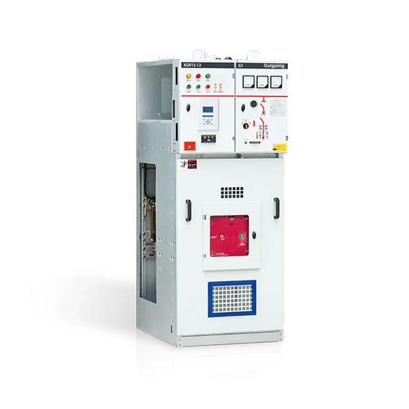
The HXGN□-12 series AC metal ring-main switchgear is a compact, extensible metal-enclosed ring-main switchgear using the FLN□-12 SF6 load switch as the main switch and air insulation for the whole cabinet, suitable for distribution automation. It features simple structure, flexible operation, reliable interlocking and easy installation, and can provide satisfactory technical solutions for various applications and user requirements.
The main switch of the HXGN□-12 series AC metal ring-main switchgear is the FLN36-12 produced by our company or the SFG SF6 load switch produced by ABB; VS1, VD4/S or ISM vacuum circuit breakers or HD4/S5 SF6 circuit breakers can also be equipped per user needs. The load switch and circuit breaker can be operated manually or motorized; with optional motorized operating mechanism, PT, CT, FTU and communication devices, distribution automation functions can be realized.
Type Designation

Service Conditions
- Altitude: not exceeding 1000 m;
- Ambient temperature: maximum +40℃; minimum -35℃;
- Ambient humidity: daily average not exceeding 95%; monthly average not exceeding 90%;
- Seismic capability: degree 8;
- The surrounding air contains no explosive or corrosive gases, and the site is free from violent vibration and shock.
Reference Standards
GB/T 191 Packaging and storage marks (ISO 780-1997, MOD)
GB 1985-2004 High-voltage AC disconnectors (IEC 62271-102:2002, MOD)
GB 3804-2004 3.6 kV~40.5 kV high-voltage AC load switches (IE060265-1:1998, MDO)
GB 3906-1991 3~35 kV AC metal-enclosed switchgear (neq IEC 60298:1990)
GB 4208-1993 Degrees of protection provided by enclosures (IP code) (eqv IEC 60529:1989)
GB/T 5582-1993 Pollution classes of external insulation of HV power equipment (eqv IEC 507:1991)
GB/T 6388 Transport packaging marks for shipping and receiving
GB 9969.1 General principles for industrial product operating manuals
GB/T11022-1999 Common technical requirements for HV switchgear and controlgear standards (eqv IEC 60694:1996)
GB/T11023-1989 SF6 gas sealing test method for HV switchgear
GB/T 13384 General technical conditions for electromechanical product packaging
GB/T 14436 General principles for industrial product guarantee documents
GB 16926-1997 AC high-voltage load switch-fuse combinations (eqv IEC 60420:1990)
JB/T 8754-1998 Model designation method for HV switchgear
DL/T 404-1997 Ordering technical conditions for indoor AC HV switchgear (neq IEC 60298:1981)
Main Technical Parameters of the Vacuum Circuit Breaker
| No. | Item | Unit | Load-switch cabinet | Combination apparatus cabinet | Circuit-breaker cabinet |
|---|---|---|---|---|---|
| 01 | Rated voltage | kV | 12 | 12 | 12 |
| 02 | Rated frequency | Hz | 50/60 | 50/60 | 50/60 |
| 03 | Rated current | A | - | - | - |
| 04 | Main busbar | A | 630 | 630 | 630 |
| 05 | Branch main busbar | A | 630 | 125 (depending on the fuse rated current) | 630 |
| 06 | Rated insulation level | kV | - | - | - |
| 07 | Power-frequency withstand voltage(between phases & to earth) | kV | 42 | 42 | 42 |
| 08 | Power-frequency withstand voltage(across the break) | kV | 48 | 48 | 48 |
| 09 | Power-frequency withstand voltage(control & auxiliary circuits) | kV | 2 | 2 | 2 |
| 10 | lightning impulse withstand voltage (between phases & to earth) | kV | 75 | 75 | 75 |
| 11 | lightning impulse withstand voltage (across the break) | kV | 85 | 85 | 85 |
| 12 | Rated short-time withstand current(r.m.s) | kA | - | - | - |
| 13 | Main circuit | kA | 20/3S | - | 25/2S |
| 14 | Earthing circuit | kA | 20/2S | - | 25/2S |
| 15 | Rated peak withstand current(peak) | kA | 50 | 80 | 63 |
| 16 | Rated short-circuit making current(peak) | kA | 50 | - | - |
| 17 | Rated short-circuit breaking current | kA | - | 31.5 | 25 |
| 18 | Rated transfer current | A | - | 1700 | - |
| 19 | Rated active load breaking current | A | 630 | - | 630 |
| 20 | Rated closed-loop breaking current | A | 630 | - | 630 |
| 21 | Rated cable-charging breaking current | A | 10 | - | 15 |
| 22 | Protection class | - | IP3X | IP3X | IP3X |
| 23 | Mechanical endurance | - | - | - | - |
| 24 | Load switch | - | 5000 | 5000 | 10000 |
| 25 | Earthing switch | - | 2000 | 2000 | 2000 |
Structure & Basic Components of the Circuit-breaker Cabinet
Basic structure
The HXGN□-1 2 circuit-breaker cabinet is mainly used as the incoming cabinet of main or backup power in ring-main supply systems and as the middle sectioning cabinet in dual-power supply systems. The circuit breaker can be VS1, VD4/S or ISM vacuum typeVacuum circuit breakeror HD4/S SF6 circuit breaker, with slightly different outline dimensions. From top to bottom, this circuit-breaker cabinet consists of the instrument room, busbar compartment, load (isolating) switch compartment, circuit-breaker compartment and cable compartment; CT, PT, surge arrester, earthing switch and relay protection devices can be configured per user needs, with reliable "five-prevention" interlocking.
The operating mechanism of the VS1 vacuum circuit breaker is of spring-energy-storage type, operable by AC or DC and also manually; it is currently the most widely used domestic vacuum circuit breaker. Its conducting circuit and operating mechanism are integrally designed with stable quality and reliable performance. The main conducting circuit is composite-insulated and small in volume. It can be installed truck-type or fixed-type. For the 630 A rated current specification, the rated short-circuit breaking current reaches 25 kA.
The VD4/S vacuum circuit breaker or HD4/S SF6 circuit breaker is designed by ABB Italy specially for ring-main switchgear; its breaking capacity is sufficient for all conditions, including normal switching of equipment or branch networks and short-circuit breaking under special circumstances. These two breakers have phases A, B, C in vertical arrangement, easy to install, small and light. The rated short-circuit breaking current reaches 25 kA.
The German ISM permanent-magnet vacuum circuit breaker is designed specially for 10 kV ring main units; it is a high-tech product with the new-technology level of 21st-century HV switchgear, whose permanent-magnet operating mechanism is an electronically controlled, online-monitoring, permanent-magnet-retained electromagnet.
Basic components
(A) Upper unit, including:
- Three-position SF6 load switch
- Operating mechanism with mechanical position indication device
- Interlocking device
- Integrated LV compartment
- Relay protection device
- Busbar compartment housing
- Busbar
(B) Middle unit, including:
- Circuit-breaker compartment
- VS1, VD4/S or ISM vacuum circuit breaker or HD4/S SF6 circuit breaker
(C) Lower unit, including:
- Earthing busbar
- Cable compartment housing
- Cable compartment bottom plate with cable supports
Through optional components, the HXGN□-12 series AC metal ring-main switchgear can be flexibly composed into various supply schemes such as incoming, outgoing, ring-main and metering.
- Integrated live-line display or plug-in interface for portable live-line display
- Auxiliary contacts 2NO+2NC at each position
- SF6 gas pressure monitor with alarm contact (SF6 load switch)
- Current transformer
- Voltage transformer
- Surge arrester
- Motorized operating mechanism (SF6 load switch)
- Lower earthing switch
- Short-circuit & earth fault indicator
- Cold-shrink indoor cable termination

Other Cabinet Types
Busbar connection cabinet
The busbar connection cabinet is used for connecting cables to the busbar; it is fitted with cable clamps to fix the cables. Current transformers, surge arresters and other components are optional. Cabinet width 375-500 mm.
Busbar section cabinet
The busbar section cabinet is always used together with the busbar riser cabinet; basic cabinet width 375 mm, equipped with one FLN36-12, FLN48-12 or SFG three-position SF6 load switch for busbar sectioning.
Busbar riser cabinet
The busbar riser cabinet connects the busbar to the bottom of the section cabinet with the load switch. With cabinet width 500 mm it can be used as a metering cabinet.
Metering cabinet
The metering cabinet is for measuring voltage, current and power; both the front upper door and lower door are fitted with special lead-seal locks for the lead seals of the power supply department.
Dual-power incoming cabinet
This equipment consists of two motorized load-switch cabinets and a complete set of automatic transfer devices. To realize automatic switching of the system, besides the traditional PT voltage acquisition, a live-line display verification mode is introduced for voltage presence judgment; according to actual conditions the equipment can be set to the following two working modes:
- One incoming line as main and the other as backup
- The two incoming lines serve as mutual backup

Auxiliary Equipment
DJD-1 short-circuit & earth fault indicator
The DJD-1 short-circuit & earth fault indicator uses logic circuits for over-current alarm and delayed reset, with manual reset also possible. Three short-circuit fault sensors are installed on the three-phase power cables respectively, and one earth fault sensor on the three-core cable; the display unit is fixed on the switchgear panel, and the sensors are connected to the display unit via optical fiber or cable. The fault indicator helps line patrol personnel quickly determine the fault section, remove the fault in time and shorten the outage time.
Condensation controller
The condensation controller consists of a temperature (humidity) sensor, a control unit and a heater; when the ambient temperature (humidity) reaches the preset range, the control unit starts the heating circuit. It monitors the temperature and humidity of the switchgear environment in real time, making the ambient indicators meet the working requirements and effectively preventing condensation. Typical technical parameters of the condensation controller are as follows:
Condensation start: 85%RH±5%RH (20℃); condensation stop: 75%RH±5%RH; response speed: typical value <35
Output: 1 × working voltage, rated power resistive load AC 220 V 3 A; heater rated power: 75-100 W
FTU & communication devices
The HXGN□-12 series AC metal ring-main switchgear can optionally be configured with DAT-1L or other models of distribution automation terminal (feeder terminal unit, FTU), bringing the switchgear into the SCADA system of distribution automation via optical fiber communication, realizing remote control, telemetry and teleindication of the switchgear. With master station software, fault isolation, restoration and network reconfiguration of the distribution network can also be realized.
DAT-1L Distribution Automation Terminal
With the optional DAT-1L distribution automation terminal and communication devices, the HXGN□-12 series AC metal ring-main switchgear can be easily integrated into the distribution automation system.
The main functions of the typical DAT-1L distribution automation terminal are as follows:
Information acquisition & processing
Including 48 teleindication channels, 8 telemetry channels, 8 remote control channels and 1 DC channel.
Parameter setting
It has remote and local parameter setting functions.
Time synchronization
Receives commands from the master or substation and keeps synchronized with the system clock.
Self-diagnosis & self-recovery
Regularly checks the important internal chips; on error, informs the substation or master and reflects the internal status; has power-on and software self-recovery functions; has a watchdog monitoring the program running state.
Fault detection
It can quickly detect faults and actively report fault information and nature to the master or substation for fault isolation, including zero-sequence over-current and over-voltage detection, line overload detection and three-phase over-current detection.

Outline & Installation Dimensions of HXGN□-12 Type II

Related Products
High-voltage switchgear of the same series and other types available:
- KYN61-40.5(Z) Metal-clad Draw-out AC Metal-enclosed Switchgear
- KYN28A-12 Metal-clad Draw-out Enclosed Switchgear
- XGN66-12(Z) Fixed Enclosed Switchgear
- XGN15-12 Box-type Fixed AC Metal-enclosed Switchgear
- HXGN17-12 Box-type Fixed AC Metal-enclosed Switchgear
- SRM-12 Fully Enclosed Fully Insulated Gas-insulated Ring Main Unit