



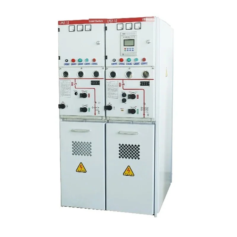
Product Overview
The XGN-12 series solid fully-insulated enclosed ring-main switchgear is a fully insulated, fully sealed, maintenance-free solid-insulated vacuum switchgear. All HV live parts are cast with epoxy resin of excellent insulation performance, integrating the vacuum interrupter, the main conducting circuit and the insulation supports into one whole, with functional units connected via fully insulated solid busbars. Therefore the whole switchgear is unaffected by the external environment, ensuring reliable operation and operator safety.
The RMU features simple structure, flexible operation, reliable interlocking and easy installation, suitable for 50 Hz, 12 kV power systems; it is widely used in industrial and civil cable ring networks and distribution terminal projects for receiving and distributing electric energy, especially for urban residential distribution, small substations, switching stations, cable branch boxes, box-type substations, industrial & mining enterprises, shopping malls, airports, subways, wind power, hospitals, stadiums, railways, tunnels and other places.
With the advantages of full insulation, full sealing and full shielding, the product is especially suitable for harsh regions such as high altitude, high temperature, humidity, severe cold and heavy pollution.
Product Classification
By switch type, they are divided into: load switch with earthing assembly (C module), load switch without earthing assembly (CB module), circuit breaker with earthing assembly (V module), circuit breaker without earthing assembly (VB module), circuit breaker tie switch (VZ module), load switch + fuse combination assembly (F module), and disconnector assembly (G module).
Type Designation

Service Conditions
- Ambient temperature: -45℃ to +45℃
- Humidity: max. average relative humidity, daily ≤95%, monthly ≤90%
- Altitude: ≤4000 m
- Seismic capability: degree 8
- Protection class: live parts sealed IP67, fuse cylinder IP67, switchgear enclosure IP3X
Features & Advantages
Environmental friendliness
All materials selected in manufacturing are non-toxic and harmless; no toxic or harmful substances are discharged during use, and the materials can be recycled after their life cycle, determining the environmental friendliness of use.
Fully insulated, fully sealed, fully shielded epoxy resin switch cylinder and fuse cylinder (epoxy resin has excellent electrical and mechanical properties and thermal characteristics, has long been used in electrical equipment with good records. The switch cylinder and fuse cylinder are formed by the epoxy resin APG process. The insulated cylinder is the key component of the solid-insulated switch, being both an insulating part and a load-bearing part, required to simultaneously meet heat resistance, weather resistance, crack resistance, high mechanical strength and good insulation strength. The cylinder is large with many inserts of various shapes, somewhat difficult to manufacture. Our company has years of experience in designing and manufacturing insulating parts, and has ensured quality mass production of this component through cylinder design, material formulation and process flow. Per user requirements, a cylinder with earthed outer shield that can be touched can be provided.)
Maintenance-free:
In the solid-insulated indoor AC HV vacuum switchgear, except the operating mechanism, the HV switch parts are in a fully sealed state, so cleaning and maintenance can be dispensed with, reducing operation and maintenance costs.
Safety:
Since shielding measures are adopted for touchable parts, electric shock accidents are eliminated and safety of use improved. The complete interlock system and clearly visible three-phase isolating openings avoid misoperation accidents. The use of SF6 gas is completely eliminated, avoiding explosion accidents of SF6 RMUs caused by reduced insulation performance and arc-extinguishing capability due to insufficient gas pressure. The reinforced phase-to-phase isolation structure avoids expansion of accidents caused by phase-to-phase or multi-circuit short circuits. A vacuum interrupter with explosion-proof performance is used, and the switch cylinder provides further protection for the switch. The auxiliary earthing switch of the load switch-fuse combination is solid-sealed in the fuse cylinder using a vacuum switch tube.
Easy operation:
The disconnector and earthing switch have only one operating handle, requiring no identification or worry about mistakes; when the circuit breaker is operating, the handles of the disconnector and earthing switch cannot be operated. The operating procedure is clear at a glance; anyone with elementary electrical knowledge can operate it without complex technical training. This makes operation extremely simple and eliminates operating errors.
Intelligence:
The switchgear reserves intelligent interfaces and sensor mounting positions; with intelligent equipment configured, it can meet the requirements of the smart grid.
Various operating mechanisms:
The switch can be fitted with spring or permanent-magnet operating mechanisms for users to choose. The XGN-12 series solid fully-insulated enclosed ring-main switchgear can be fitted with spring or permanent-magnet mechanisms, further enriching the applicable scenarios of the product.
Applicable Standards
- ◇ Q/GDW 730-2012 "Technical conditions for 12 kV solid-insulated ring main units"
- ◇ GB1984 "AC high-voltage circuit breakers"
- ◇ GB3804 3.6 kV-40 kV "AC high-voltage load switches"
- ◇ GB1958 "AC high-voltage disconnectors and earthing switches"
- ◇ GB4208 "Degrees of protection provided by enclosures (IP code)"
- ◇ GB 16926 AC high-voltage load switch-fuse combinations
- ◇ GB/T15166.2 High-voltage AC fuses, Part 2: current-limiting fuses
- ◇ GB/T7354 "Partial discharge measurement"
- ◇ GB/T11022 "Common technical conditions for high-voltage switchgear and controlgear standards"
- ◇ GB3906 "3.6-40.5 kV AC metal-enclosed switchgear and controlgear"
Main Technical Parameters
| Item | Unit | Parameters |
|---|---|---|
| Normal | - | - |
| Rated voltage | kV | 12 |
| Rated frequency | Hz | 50 |
| Power-frequency withstand voltage | kV/min | 42/48 |
| Lightning impulse voltage | kV | 75/85 |
| Arcing duration | s | ≥0.5 |
| Primary parts protection class (except metering cabinet) | - | IP67 |
| Cabinet protection class | - | IP4X |
| Protection class between compartments | - | IP2X |
| Operating power supply voltage | - | DC24、48、110、220 |
| AC110、220 | ||
| Busbar system | - | - |
| Rated current | A | 630(1250) |
| Rated short-time withstand current | kA/s | 20/4(25/4) |
| Rated peak withstand current | kA | 50(63) |
| Rated peak withstand current | kA | 50 |
| Load-switch unit | - | - |
| Rated current | A | 630 |
| Rated short-circuit making current | kA | 50 |
| Rated short-time withstand current | kA/s | 20/4 |
| Mechanical life of load switch | operations | - |
| Electrical life of load switch | operations | E3 |
| Partial discharge | PC | ≤5 |
| Circuit-breaker unit | - | - |
| Rated current | A | 630(1250) |
| Rated short-circuit breaking current | kA | 20(25) The switch can be fitted with spring or permanent-magnet mechanisms per user choice. |
| Item | Unit | Parameters |
|---|---|---|
| Rated short-circuit making current | kA | 50(63) |
| Rated short-time withstand current | kA/s | 20/4(25/4) |
| Mechanical life of circuit breaker | operations | 20000 |
| Electrical life of circuit breaker | operations | E2 |
| Rated operating sequence | - | O-0.3s-CO-180s-CO |
| Partial discharge | PC | ≤5 |
| Load switch-fuse combination unit | - | - |
| Rated current (max.) | A | 200 |
| Rated short-circuit breaking current | kA | 31.5 |
| Rated short-circuit making current | kA | 80 |
| Partial discharge | PC | 3150 |
| Disconnector | - | - |
| Rated current | A | 630/1250 |
| Rated short-time withstand current | kA | 20/25 |
| Rated short-time duration | s | 4 |
| Rated peak withstand current | kA | 50/63 |
| Mechanical endurance | operations | 3000 |
| Earthing switch | - | - |
| Rated current | A | 630/1250 |
| Rated short-time withstand current | kA | 20/25 |
| Rated short-time duration | - | 4 |
| Rated peak withstand current | kA | 50/63 |
| Rated short-circuit making current (peak) | kA | 50 |
| Number of rated short-circuit making operations | operations | 2 |
| Mechanical endurance | operations | 3000 |
Application Fields
Cold regions: no SF6 gas is used, so low-temperature SF6 operation is not a concern; normal operation is possible even at -45℃.
Plateau regions: no need to consider the influence of plateau atmospheric pressure on insulation performance.
Strong wind-sand regions: the solid-insulated RMU body has protection class IP67, and the control circuit room is specially treated to ensure long-term operation in strong wind-sand regions.
Coastal humid regions: epoxy resin sealing, moisture-resistant and salt-fog corrosion resistant, ensuring long-term use in coastal areas.
Regions with high environmental requirements: the influence of SF6 gas on atmospheric warming has drawn high attention; the solid-insulated RMU eliminates SF6 gas, causing no pollution or harm to the environment or people.
Smart grid: since the main switch and disconnector can both be motorized, with the intelligent controller developed by our company, the switchgear and substation site can be remotely controlled, telemetered and communicated, supporting both distributed and centralized control. With the remote control, telemetry and communication functions of the intelligent controller, the XGN-12 series solid fully-insulated enclosed ring-main switchgear can meet the application requirements of distribution automation.
Design Schemes

Product Structure & Working Principle
The core structure of the solid-insulated RMU is as shown: the XGN-12 series solid fully-insulated enclosed ring-main switchgear casts the vacuum interrupter, the main conducting circuit and the insulation supports into one body, structurally avoiding condensation and pollution flashover hazards.

Structural Features of the Solid-insulated RMU Core
Vacuum interrupter
The vacuum circuit breaker can break short-circuit currents for overload and short-circuit protection of circuits and electrical equipment. With small contact gap, short arcing time, slight contact burn when breaking fault currents, small required operating energy and fast action, it also has the advantages of small volume, light weight, little maintenance work, fire and explosion safety and low operating noise; it is an ideal circuit breaker to replace oil circuit breakers and SF6 circuit breakers, widely used in distribution systems such as high-frequency heating in power, metallurgy and communication industries. The vacuum interrupter is the key component and the heart of the vacuum circuit breaker, essentially determining its main performance.
Solid insulation system
The solid-sealed pole cast by the APG process encapsulates the vacuum interrupter and current-carrying conductors such as upper and lower outgoing seats into one whole. The disconnector is installed in the cavity of the solid-sealed pole, making solid insulation the main insulation between phases. The single-phase insulated busbar design avoids severe faults such as phase-to-phase and to-earth faults. The busbar is extensible, realizing unlimited extension of functional units.
Three-position switch
All switchgear cabinets are fitted with a three-position switch. The three-position switch is built into the solid-sealed pole together with the main switch. Three phases are linked and can be operated to the working / isolated / earthed positions. It is mechanically interlocked with the main switch: only when the main switch is open can the three-position switch act; moreover, the working and earthing positions of the three-position mechanism are interlocked with each other — when the switch is at the working position the earthing-side hole is locked, and when at the earthing position the working-side hole is locked.
Operating mechanism
The circuit-breaker operating mechanism is a spring mechanism with simple structure, reliable action, compact size and maintenance-free; the closing power can be adjusted up or down per user requirements; the mechanism can store energy, close and open manually, or store energy and open/close motorized, convenient for users
The three-position switch operating mechanism adopts an over-center spring design for fast opening/closing, capable of breaking and making certain load currents; besides manual operation, the three-position mechanism can also be motorized, enabling intelligent remote control of isolation and earthing, greatly facilitating use.
Structural features of the solid-insulated RMU
The solid-insulated RMU is a small GIS switchgear cabinet with the following structure:
- a. The HV load switch and HV live parts are sealed in a gas-free epoxy plastic insulating cylinder housing with vacuum interrupter arc extinction, small in volume and reliable in arc extinction. The load switch comes with an earthing switch, having closed, open and earthed positions, and the earthing switch also functions as an isolating switch.
- b. It can accommodate 1~5 load-switch units or 1~5 circuit-breaker units. Each unit leads out through three HV bushings, convenient for cable connection.
Product Structural Characteristics
- c. The sealed tank is made of imported materials; strict sealing measures are taken at the mechanism connections and HV bushings with good performance.
- d. The HV bushings and HV insulating cylinders are made of imported epoxy resin by the APG process; the insulating cylinder and the HV bushings are assembled with tight interference fit via silicone-rubber sleeves, providing good sealing.
- e. Each way has an independent operating mechanism installed on the front of the cabinet, with various mechanical interlocking functions.
- f. The load switch and earthing switch are fitted with spring operating mechanisms; the load switch can be operated manually or motorized, and the earthing switch not only earths but also isolates, operated only manually.
- g. The circuit breaker is fitted with a permanent-magnet operating mechanism: motorized closing/opening, manual opening but no manual closing. The circuit breaker can also be fitted with a spring mechanism, both manual and motorized, with a reserved distribution automation interface.
- h. The RMU panel has a viewing window for directly observing the open/close state of the isolating switch break.
- i. Each RMU unit consists of three separate insulating cylinders in parallel, easy to install and replace; the biggest advantage is the avoidance of phase-to-phase discharge.
Features of the Solid-insulated Fully-enclosed RMU
- a. The main components of the solid-insulated fully-enclosed RMU are the insulating cylinder and the vacuum interrupter.
- b. The solid insulating material is imported epoxy plastic with thickness not less than 10 mm, strong corrosion resistance and high insulation capability; the internal spacing is greater than 150 mm, phases separated individually and connected via the bottom mounting frame, with flexible combination, simple and rational structure, and elegant appearance.
- c. No removable fasteners on the tank surface (good anti-theft performance); the tank has protection class IP33 with good rain protection.
- d. The roof has vents: the air inlet is at the lower part of the tank with a dust filter, and the outlet is on the top hidden under the eaves, forming bottom-up air convection for good heat insulation and ventilation; the roof has a drainage inclination.
- e. The tank has a sealed floor at the cable entry to prevent moisture in the cable trench from entering the tank.
- f. The door is sealed with sealing strips; the lock is rain-proof; a limit rod fixes the door when open.
- g. The switches in the tank are of solid-insulated fully-sealed structure, no heater needed; cable heads can be touchable or non-touchable per user requirements, immune to immersion.
Operating Mechanism & Operation
a. Each way of load switch and earthing switch in the ring-main unit is fitted with an independent spring operating mechanism mounted on the front panel, operable manually or motorized. Each way on the panel has two operating holes for the load switch and the earthing switch respectively. The vacuum circuit breaker is fitted with an integrated permanent-magnet operating mechanism and spring operating mechanism.
Load switch operating instructions
Energizing operation
First close the isolating earthing switch: insert the operating handle into the earthing operating hole (while the isolating switch is in the earthed closed state), rotate counterclockwise to open the earthing switch, then insert the handle into the isolating operating hole and rotate counterclockwise to close the isolating switch.
Then close the load switch: insert the operating handle into the main switch operating hole and rotate about 2 turns counterclockwise; the main switch closes.
De-energizing operation
- a. First open the load switch: turn the opening knob counterclockwise to open the switch.
- b. Then open the isolating earthing switch: insert the handle into the isolating mechanism operating hole and rotate clockwise to open the isolating switch, then insert the handle into the earthing operating hole and rotate clockwise to close the earthing switch.
Circuit-breaker operating instructions
- c. Circuit-breaker operating instructions
- d. Mechanical interlock: there are mechanical interlocks among the load switch, circuit breaker and earthing switch. When the load switch or circuit breaker is closed, the earthing switch cannot be opened or closed; when the earthing switch is closed, the load switch and circuit breaker cannot be opened or closed.
- e. Installation and replacement of the fuse
- (1) Close the earthing switch first.
- (2) Lift the operating handle forcibly and rotate counterclockwise to release the pin from the slot.
- (3) Put the striker mechanism into the fuse barrel with the pin in the slot, rotate clockwise so that the operating handle is parallel to the panel, then press the handle down firmly.
- (4) It can be opened only when the load switch is earthed.
Standard configurations
- 630 A insulated busbar
- Load earthing switch
- Operating mechanism of load earthing switch
- Load / earthing switch
- Outgoing bushings at the front horizontal position, 630 A front-connected cable head
- Live-line indicator integrated with phasing hole, complying with ISO61958
- Solid-insulated voltage transformer
- Elbow connector (with cable)
- Voltage transformer protection fuse
- Earthing busbar
- Meeting the five-prevention interlock
Optional configurations
- Heater
- Voltmeter

Standard configurations Standard configurations
- 630, 1250 A insulated busbar
- Vacuum circuit breaker
- Operating mechanism of the vacuum circuit breaker
- Isolating / earthing switch
- Operating mechanism of isolating / earthing switch
- Mechanical interlock of circuit breaker and earthing switch
- Independent position indication of circuit breaker and earthing switch
- Outgoing bushings at the front horizontal position, front-connected cable head
- Live-line indicator integrated with phasing hole, complying with ISO61958
- Earthing busbar
- Microprocessor protection device
- Meeting the five-prevention interlock
Optional configurations
- Auxiliary contacts
- Program lock
- Heater
- Rear-connected surge arrester
- Rear-connected cable head
- Incoming live earthing interlock
- Earth fault indicator
- Bushing-type current transformer and ammeter, active power meter, reactive power meter

Circuit-breaker tie cabinet
Standard configurations
- 630 A, 1250 A insulated busbar
- Vacuum circuit breaker
- Operating mechanism of the vacuum circuit breaker
- Isolating / earthing switch
- Operating mechanism of isolating / earthing switch
- Mechanical interlock of circuit breaker and earthing switch
- Independent position indication of circuit breaker and earthing switch
- Outgoing bushings at the front horizontal position, front-connected cable head (with cable)
- Live-line indicator integrated with phasing hole, complying with ISO61958
- Earthing busbar
- Microprocessor protection device
- Meeting the five-prevention interlock
Optional configurations
- Auxiliary contacts
- Program lock
- Heater
- Rear-connected surge arrester
- Rear-connected cable head
- Incoming live earthing interlock
- Earth fault indicator
- Bushing-type current transformer and ammeter, active power meter, reactive power meter

Circuit-breaker cabinet
Standard configurations
- 630, 1250 A insulated busbar
- Vacuum circuit breaker
- Operating mechanism of the vacuum circuit breaker
- Isolating earthing switch
- Operating mechanism of isolating / earthing switch
- Mechanical interlock of circuit breaker and earthing switch
- Independent position indication of circuit breaker and earthing switch
- Outgoing bushings at the front horizontal position, front-connected cable head
- Live-line indicator integrated with phasing hole, complying with ISO61958
- Earthing busbar
- Microprocessor protection device
- Meeting the five-prevention interlock
Optional configurations
- Auxiliary contacts
- Program lock
- Heater
- Rear-connected surge arrester
- Rear-connected cable head
- Incoming live earthing interlock
- Earth fault indicator
- Bushing-type current transformer and ammeter, active power meter, reactive power meter

Riser cabinet
Standard configurations
- 630 A, 1250 A insulated busbar
- Outgoing bushings at the front horizontal position, front-connected cable head (with cable)
- Live-line indicator integrated with phasing hole, complying with ISO61958
- Earthing busbar
Optional configurations
- Heater
- Rear-connected surge arrester
- Rear-connected cable head
- Earth fault indicator
- Bushing-type current transformer and ammeter, active power meter, reactive power meter

Circuit-breaker tie cabinet
Standard configurations
- 630 A, 1250 A insulated busbar
- Vacuum circuit breaker
- Operating mechanism of the vacuum circuit breaker
- Isolating / earthing switch
- Operating mechanism of isolating / earthing switch
- Mechanical interlock of circuit breaker and earthing switch
- Independent position indication of circuit breaker and earthing switch
- Outgoing bushings at the front horizontal position, front-connected cable head (with cable)
- Live-line indicator integrated with phasing hole, complying with ISO61958
- Earthing busbar
- Microprocessor protection device
- Meeting the five-prevention interlock
Optional configurations
- Auxiliary contacts
- Program lock
- Heater
- Rear-connected surge arrester
- Rear-connected cable head
- Incoming live earthing interlock
- Earth fault indicator
- Bushing-type current transformer and ammeter, active power meter, reactive power meter
Outline & Installation Dimensions

14
Outline & Installation Dimensions

15
Transport & storage
- The packed RMU can be handled by electric forklift or crane; the RMU is fitted with lifting rings for hoisting during handling。The rope for hoisting shall not be shorter than 2 m。
- Before installation on site, the RMU shall be placed in a dry, ventilated, dust-free place。If covered with plastic bags, the bottom shall be left open for ventilation。
Use & maintenance
a. Checks before use: before using the RMU, the following checks must be performed for personal and equipment safety
- Check whether the main circuit and earthing circuit are correctly connected。
- Check whether the mechanical interlocks are correct and reliable。
- Check whether the load switch and earthing switch in the RMU operate flexibly and correctly。
- Check whether the HV cable connections are correct and reliable。
b. Operation
- Put the RMU into operation following the specified operating sequence。
c. Maintenance: based on the following advantages, this equipment requires no daily maintenance
- All live parts are installed in epoxy plastic insulating cylinders。
- All operating mechanism parts outside the epoxy plastic insulating cylinders are electroplated。
- The main shaft is supported by copper bushings and can work continuously and effectively even without lubricant。
Note: if the RMU has a fault, do not attempt to open and repair it with drills, cutting machines or other tools; such operations can only be performed by our company personnel。
Accompanying documents & accessories
The following documents and accessories are provided with the product when leaving the factory:
- Product installation & operation manual
- Factory test report
- Product certificate
- Packing list
- Operating handle
- Other accessories
Related Products
High-voltage switchgear of the same series and other types available:
- KYN61-40.5(Z) Metal-clad Draw-out AC Metal-enclosed Switchgear
- KYN28A-12 Metal-clad Draw-out Enclosed Switchgear
- XGN66-12(Z) Fixed Enclosed Switchgear
- XGN15-12 Box-type Fixed AC Metal-enclosed Switchgear
- HXGN-12 Box-type Fixed AC Metal-enclosed Switchgear
- HXGN17-12 Box-type Fixed AC Metal-enclosed Switchgear