



Product Overview
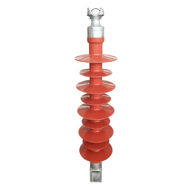
The FPQ-35/10 composite pin insulator has a rated voltage of 35 kV and a rated mechanical load of 10 kN, and is used for pin-type insulation support on high-voltage lines.
The insulator is suitable for high-voltage line facilities. It offers excellent hydrophobicity, ageing resistance, tracking resistance and erosion resistance, together with very high tensile and bending strength. It features high mechanical strength, good impact, vibration and anti-brittle performance, and is light in weight and easy to install. Its top and bottom mounting dimensions are identical to those of the corresponding porcelain pin insulators, so the two can be used interchangeably. The product withstands bending loads of 5-12.5 kN. As a pin-type insulation support for 35 kV lines, the FPQ-35/10 composite pin insulator is light in weight and easy to install, and can replace porcelain pin insulators of the same mounting dimensions.
Type Designation
In the type designation, F stands for composite insulation, P for the pin-type construction, and Q for the ball-and-socket coupling. The figure 35 before the slash indicates the rated voltage of 35 kV, and the figure 10 after the slash the rated mechanical load of 10 kN. This model has a structural height of 420 mm, a minimum nominal creepage distance of 1160 mm, a lightning impulse withstand voltage (peak) of 200 kV and a shed diameter of 122/92 mm; it is intended for pin-type insulation support on 35 kV distribution lines, being light in weight, cleaning-free and stable under polluted conditions. With a minimum nominal creepage distance of 1160 mm, the FPQ-35/10 composite pin insulator operates reliably in polluted areas and reduces cleaning and maintenance.
Product Photos

Main Technical Parameters
Performance complies with GB/T20142-2006 and IEC 61952.
Main technical parameters of 10-35kV composite pin insulators
| Model | Rated voltage (kV) | Rated mechanical load (kN) | Structural height (mm) | Min. arcing distance (mm) | Min. nominal creepage distance (mm) | Shed diameter (mm) | Lightning impulse withstand voltage, peak (kV) | 1-min power-frequency wet withstand voltage, r.m.s. (kV) |
|---|---|---|---|---|---|---|---|---|
| FPQ-10/4T20 | 10 | 4 | 215 | 125 | 300 | 140/115 | 75 | 42 |
| FPQ4-10/4T16 | 10 | 4 | 250 | 165 | 420 | 140/115 | 105 | 42 |
| FPQ4-10/5T20 | 10 | 5 | 250 | 165 | 420 | 140/115 | 105 | 42 |
| FPS-10S/5 | 10 | 5 | 250 | 180 | 380 | 90 | 105 | 42 |
| FPQ-20/12.5 | 20 | 12.5 | 380 | 290 | 780 | 140/110 | 125 | 50 |
| FPQ-12/5 | 12 | 5 | 250 | 150 | 370 | 115 | 95 | 42 |
| FPQ-35/10 | 35 | 10 | 420 | 350 | 1160 | 122/92 | 200 | 95 |
Main technical parameters of 35-220kV composite anti-wind deflection insulators
| Model | Rated voltage (kV) | Rated mechanical bending load (kN) | Rated mechanical load (kN) | Structural height (mm) | Min. arcing distance (mm) | Min. nominal creepage distance (mm) | Lightning impulse withstand voltage, peak (kV) | 1-min power-frequency wet withstand voltage, r.m.s. (kV) | Connection marking |
|---|---|---|---|---|---|---|---|---|---|
| FSP-35/0.8-AQ(TQ) | 35 | 0.8 | 100 | 710±15 | 470 | 1380 | 230 | 95 | 16 |
| FSP-66/0.8-AQ(TQ) | 66 | 0.8 | 100 | 950±15 | 710 | 2200 | 410 | 185 | 16 |
| FSP-110/0.8-AQ(TQ) | 110 | 0.8 | 100 | 1440±15 | 1200 | 3800 | 550 | 230 | 16 |
| FSP-220/0.8-AQ(TQ) | 220 | 0.8 | 100 | 2250±30 | 2050 | 7280 | 1000 | 395 | 16 |
Notes: 1. The above parameters are typical values for composite pin / anti-wind deflection insulators; the specific height, creepage distance and mounting dimensions can be customised according to project requirements. 2. In the table, the suffix T denotes the steel cross-arm mounting structure and Q denotes the ball coupling. 3. Performance complies with GB/T20142-2006 and IEC 61952.
Related Products
Composite pin insulators of the same series:
Other composite insulators: