



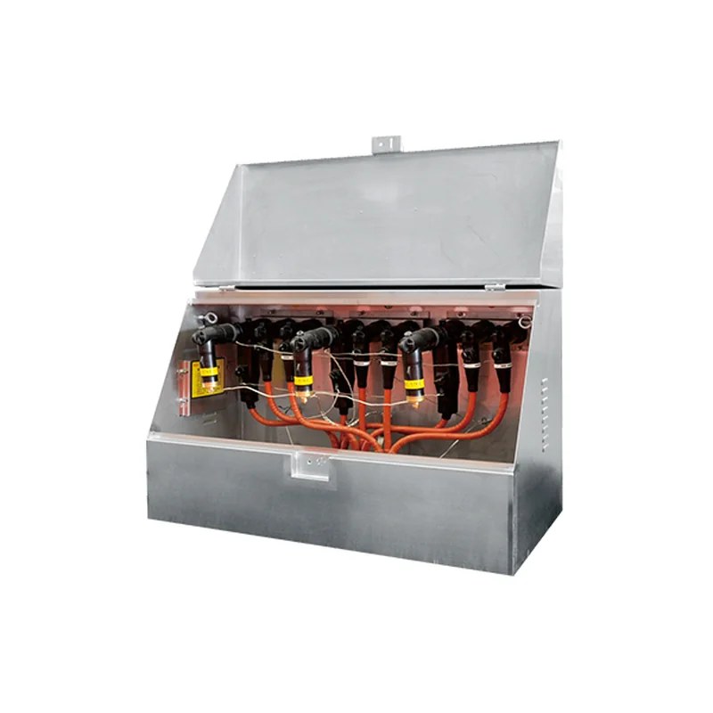
American Cable Branch Box
The American-style cable branch box produced by our company, with excellent performance, standardized design and elegant appearance, is widely used as cable-ization equipment in cable distribution networks, and is generally recognized in industrial parks, residential areas, densely populated urban areas, commercial centers, high-rise buildings and other places. It is characterized by a single door and horizontal multi-way busbars, with outstanding advantages such as small width, flexible combination, full insulation and full sealing. By rated current it is generally divided into 600 A main circuits and 200 A branch circuits. The 600 A main circuit adopts threaded bolted connections; the 200 A branch circuit adopts plug-in (elbow) connections and can be plugged or unplugged under load. The DFW-12/630A American cable branch box has a rated voltage of 15 kV and rated currents of 200 A (branch network) / 600 A (main network).
Type Designation

Main Technical Parameters
| Item | 200 A (branch network) | 600 A (main network) |
|---|---|---|
| Rated voltage | 15kV | 15/25kV |
| Rated current | 200A | 600A |
| Rated short-time withstand current | 16kA/1s | 40kA/1s |
| 1-min power-frequency withstand voltage | 42kV | 42kV |
| 15-min DC withstand voltage | 53kV | 78kV |
| Lightning impulse withstand voltage | 95kV | 125kV |
| Minimum corona inception voltage | 11kV | 19kV |
Normal Service Conditions
Ambient temperature: maximum +40℃, minimum -30℃
Wind speed: equivalent to 34 m/s (not exceeding 700 Pa)
Humidity: daily average relative humidity not exceeding 95%, monthly average not exceeding 95%
Anti-vibration: horizontal acceleration not exceeding 0.4 m/s², vertical acceleration not exceeding 0.15 m/s²
Site inclination: not more than 30°
Installation environment: the surrounding air shall not be obviously polluted by corrosive or combustible gases or water vapor, and the site has no violent vibration
Note: If ordering beyond the above conditions, please consult our company.
Main Technical Parameters
| American tank branch box model | Scheme | Connection scheme | Outline dimensions L×W×H |
|---|---|---|---|
| DFW12/11-200 | 200Ax2 |  |
800x400x760 |
| DFW12/12-200 | 200Ax3 | 1100x400x760 | |
| DFW12/13-200 | 200Ax4 | 1300x400x760 | |
| DFW12/11-600 | 600Ax2 | 900x560x760 | |
| DFW12/12-600/200 | 600Ax2 200AX1 |
900x560x760 | |
| DFW12/13-600/200 | 600Ax2 200Ax2 |
900x560x760 | |
| DFW12/12/600 | 600Ax3 | 1200x560x760 | |
| DFW12/14-600/200 | 600Ax3 200Ax2 |
1200x560x760 | |
| DFW12/15-600/200 | 600Ax3 200Ax3 |
1200x560x760 | |
| DFW12/13-600 | 600Ax4 | 1500x560x760 | |
| DFW12/16-600/200 | 600Ax4 200Ax3 |
1500x560x760 | |
| DFW12/17-600/200 | 600Ax4 200Ax4 |
1500x560x760 | |
| DFW12/13-600/200 | 600Ax1 200Ax3 |
1500x560x760 | |
| DFW12/14-600/200 | 600Ax1 200Ax4 |
1500x560x760 | |
| DFW12/13-600/200 | 600Ax2 200Ax2 |
1500x560x760 | |
| DFW12/13-600/200 | 600Ax3 200Ax1 |
1500x560x760 | |
| DFW12/14-600(200 | 600Ax3 200Ax2 |
1500x560x760 | |
| DFW12/15-600/200 | 600Ax3 200Ax3 |
1500x560x760 | |
| DFW12/16-600/200 | 600Ax3 200Ax4 |
1500x560x760 | |
| DFW12/15-600/200 | 600Ax2 200Ax4 |
1500x560x760 | |
| DFW12/14-600t200 | 600Ax2 200Ax3 |
1500x560x760 |
American Cable Branch Box Structure Examples
If space is limited and a cable branch box cannot be placed, cable connectors can be directly combined to form multi-way cable branches (without busbars; see the examples below for the connection method), placed in cable trenches or other locations.
Example 1: four-way incoming/outgoing (2x600A+2x200A)
Each group consists of two T-II type cable connectors, two elbow connectors and one intermediate joint. The 200 A side of the T-II connector connects to the elbow connector (the other side connects to a fully insulated metal-oxide surge arrester). See the figure below for dimension examples:

Example 2: three-way incoming/outgoing (3x600A)
Each phase consists of three T-type cable connectors and two intermediate joints. See the figure below for dimensions and examples: the DFW-12/630A American cable branch box can flexibly combine incoming/outgoing lines in schemes such as 2x600A+2x200A.

Note: Cable branches can be extended or reduced as needed, either covered by a tank or directly buried in cable trenches. The tank dimensions and connection schemes of the DFW-12/630A American cable branch box can be selected with reference to the table above.
American Cable Branch Box Foundation Drawings
American 600 A

American 200 A

7

Related Products
Cable branch boxes of the same series and other types available: