



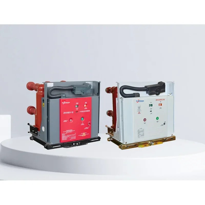
Overview
The ZV1(VS1)-12 series indoor solid-sealed high-voltage vacuum circuit breaker adopts a solid-insulation structure. By using advanced epoxy solid-sealing technology, the vacuum interrupter, main conductive circuit and insulation support are integrated into a single sealed pole for the first time, fundamentally solving the environmental-withstanding problem of the vacuum circuit breaker and widening its application. The integrated sealed pole adopts a self-convection patented ventilation technology, cleverly resolving the heat-dissipation difficulty brought by the solid-insulation structure. This series is the first circuit breaker in China to realize the maintenance-free concept. Its long-life vacuum interrupter and the epoxy-cast solid-sealing technology ensure the maintenance-free integrated sealed pole; meanwhile a high-reliability permanent-magnet operating mechanism ensures the maintenance-free operating mechanism, and the electronic control part replaces the traditional auxiliary switch with a photoelectric proximity switch, with a fully electronic power supply and an intelligent control unit ensuring the maintenance-free electronic control part.
Type Designation
Normal Service Environment
For the ZV1(VS1)-12 vacuum circuit breaker, the normal service environment is as follows: The ZV1(VS1)-12 vacuum circuit breaker uses epoxy solid-sealing for the vacuum interrupter and the main conductive circuit, and provides rated short-circuit breaking currents of 20/25 kA, 31.5 kA and 40 kA for rated currents of 630 A, 1250 A and 1600 A.
1. Ambient temperature: not higher than 40°C, not lower than -10°C (storage and transportation allowed at -30°C).
2. Altitude: not exceeding 1000m. At higher altitudes the rated insulation level shall be increased accordingly.
3. Relative humidity: daily average not greater than 95%; saturated vapor pressure daily average not greater than 2.2×10³ MPa, monthly average not greater than 1.8×10³ MPa.
4. Seismic intensity: not exceeding magnitude 8.
5. Sites free from fire, explosion, severe pollution, chemical corrosion and violent vibration.
Outline and Mounting Dimensions
Technical Parameters
For the ZV1(VS1)-12 vacuum circuit breaker, the normal service environment is as described above, and the main technical parameters are listed in the table below.
| No. | Item | Unit | Data | ||||
|---|---|---|---|---|---|---|---|
| 1 | Rated voltage | kV | 12 | ||||
| 2 | Rated maximum operating voltage | kV | 12 | ||||
| 3 | Rated current | A | 63 | 6301250 | 12501600 | ||
| 16002000 | 20002500 | ||||||
| 1250 | 25003150 | 31504000 | |||||
| 4 | Rated short-circuit breaking current (rated thermal stabilizing current, r.m.s.) | kA | 20/25 | 31.5 | 40 | ||
| 5 | Rated short-circuit making current (peak) | kA | 50/63 | 80 | 100 | ||
| 6 | Rated peak withstand current (rated dynamic stabilizing current, peak) | kA | 50/63 | 80 | 100 | ||
| 7 | Rated short-time withstand current (4s) | kA | 20/25 | 31.5 | 40 | ||
| 8 | Rated power-frequency withstand voltage (before/after breaking) / 1 min | kV | 42 to ground (48 across open gap) | ||||
| Rated lightning impulse withstand voltage (peak, before/after breaking) | 75 to ground (85 across open gap) | ||||||
| 9 | Rated short-circuit duration | 4 | |||||
| 10 | Rated operating sequence | O-0.3s-CO-180s-CO | |||||
| 11 | Mechanical endurance | times | 20000 | ||||
| 12 | Number of rated short-circuit breaking operations | times | 50 | ||||
| 13 | Rated closing voltage of operating mechanism (DC) | AC, DC110, 220 | |||||
| 14 | Rated opening voltage of operating mechanism (DC) | AC, DC110, 220 | |||||
| 15 | Contact gap | mm | 11±1 | ||||
| 16 | Over-travel (contact spring compression) | mm | 3.5±0.5 | ||||
| 17 | Three-phase open/close bounce time | ms | ≤2 | ||||
| 18 | Contact closing bounce time | ms | ≤2 | ||||
| 19 | Average opening speed | m/s | 0.9~1.2 | ||||
| Average closing speed | m/s | 0.5~0.8 | |||||
| 20 | Opening time | at maximum operating voltage | s | ≤0.05 | |||
| 21 | at minimum operating voltage | ≤0.08 | |||||
| 22 | Closing time | 0.1 | |||||
| 23 | Main-circuit resistance per phase | uΩ | 630≤50 | 1250≤45 | |||
| 24 | Allowable cumulative contact wear thickness | mm | 3 | ||||


Related Products
Circuit breakers of the same series and other types available for selection: