



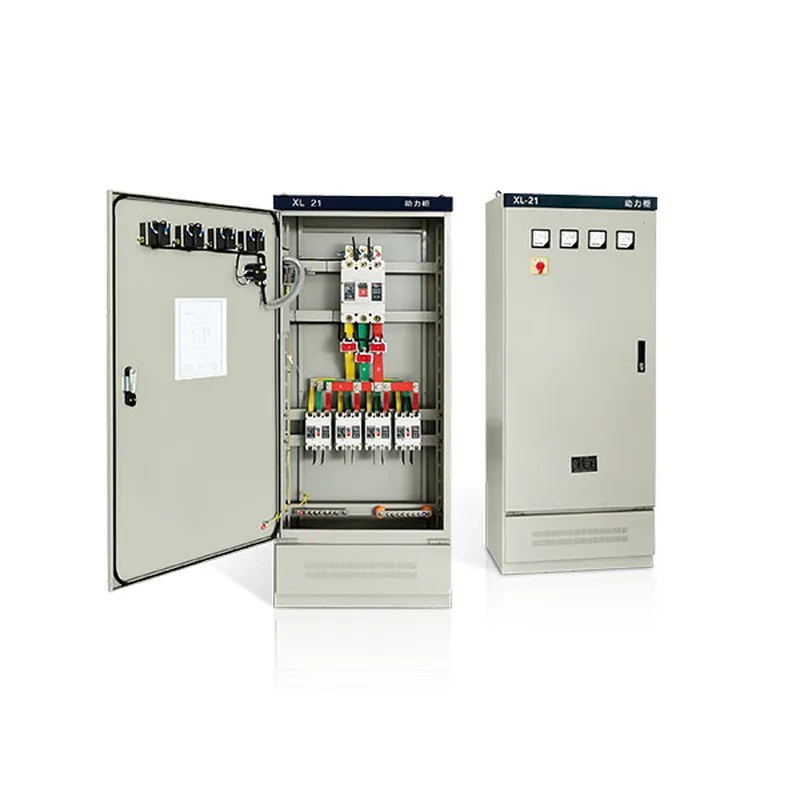
Product Overview
The XL-21 low-voltage power distribution cabinet is used in power plants and industrial and mining enterprises for power distribution in three-phase four-wire or three-phase five-wire systems with AC voltage of 500 V and below. The XL-21 low-voltage power distribution cabinet is an indoor unit installed against the wall and serviced from the front.
Type Designation

Structural Features
The XL-21 low-voltage power distribution cabinet is of enclosed type, with a housing bent from steel plate; the operating handle of the knife switch is mounted on the upper part of the right column at the front of the box and can be used for power source changeover. A voltmeter is fitted on the front of the box to indicate the busbar voltage. There is a door at the front; when the door is opened all equipment inside is exposed for easy inspection and maintenance. The box uses domestically designed components and features a compact structure, convenient maintenance and flexible combination of circuit schemes. In addition to air circuit breakers and fuses for short-circuit protection, the box is also fitted with contactors and thermal relays, and operating buttons and indicator lamps can be mounted on the front door.
Service Conditions
- Ambient temperature: -50 ℃ to +40 ℃, with the average temperature within 24 h not exceeding +36 ℃;
- Altitude: not exceeding 2000 m;
- Relative humidity: not exceeding 50% at an ambient air temperature of +40 ℃;
- A higher relative humidity is permissible at lower temperatures (for example 90% at +20 ℃); moderate condensation due to temperature changes is allowed;
- The inclination of the equipment to the vertical plane during installation shall not exceed 5°, and the equipment shall be installed in a place free from violent vibration, shock and corrosion.
Operation, Maintenance & Servicing
After installation or servicing, the power distribution cabinet shall be subjected to the following inspections and tests before being put into operation (the inspection and test after servicing depend on the nature of the servicing).
- Check whether the electrical equipment and secondary wiring installed inside the power distribution cabinet comply with the drawings.
- Check whether the knife switches and air switches used for operation are flexible and free from jamming.
- Check whether the contacts of the installed electrical equipment are in good condition and whether they meet the requirements of the equipment itself.
- Check that there are no foreign objects inside the power distribution cabinet and that the fixing screws in all parts are not loose.
Outline & Installation Dimensions
- The outline and installation dimensions of the type A structure of the power distribution cabinet are shown in Figure 1.
- The outline and installation dimensions of the type B structure of the power distribution cabinet are shown in Figure 2.
4

Main Technical Parameters
Fuse-switch combination
| Model | Rated current (A) | Rated current of fuse link (A) | Remarks |
|---|---|---|---|
| HR3-400/34 | 400 | 150,200,250,300,350,400 | No fuse link when isolating blades are fitted |
Current transformer
| Model | Rated current (A) | Secondary current (A) | Remarks |
|---|---|---|---|
| LM-0.5 | 75、100、150、200、300、600 | 5 | - |
Fuse
| Model | Fuse | Rated current of fuse link (A) | Remarks |
|---|---|---|---|
| RL1-15 | 15 | 2、4、5、6、10、15 | - |
| RL1-60 | 60 | 20、25、30、35、40、50、60 | - |
| RL1-100 | 100 | 30、40、50、60、80、100 | - |
| RL1-200 | 200 | 80、100、120、150、200 | - |
| RL1-400 | 400 | 150、200、250、300、350、400 | - |
AC contactor
| Model | Rated current (A) | Coil voltage (V) | Remarks |
|---|---|---|---|
| CJ10-10 | 10 | AC 110 220 380 |
- |
| CJ10-20 | 20 | - | |
| CJ10-40 | 40 | - | |
| CJ10-80 | 80 | - | |
| CJ10-150 | 150 | - |
Ordering Information
The customer shall provide the following information when ordering:
- ◆Primary circuit scheme and single-line system diagram;
- ◆Developed secondary circuit diagram;
- ◆Detailed specifications and data of the various electrical devices installed in each box;
- ◆When ordering the type B structure, the arrangement drawing and layout plan of the power distribution cabinets shall be provided.

Related Products
Low-voltage switchgear of the same series and other types available for selection: