



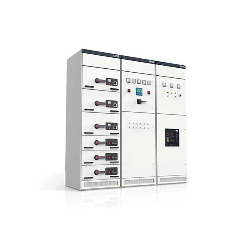
Product Overview
The MNS low-voltage withdrawable switchgear (hereinafter referred to as the switchgear) was developed by our company with reference to the MNS series low-voltage switchgear of ABB Switzerland and through comprehensive improvement; it is currently one of the best low-voltage withdrawable switchgear products in China. The product is composed of standardised, serialised modules, and the drawers are fitted with reliable mechanical interlocks, making it safer and more reliable for users.
This switchgear is suitable for AC 50 (60) Hz three-phase five-wire power supply systems with rated operational voltage of 400 V and 660 V and rated current of 5000 A and below. It can be used in power plants, substations, industrial and mining enterprises, hotels and office buildings, airports, docks and radio & television communication centres for the control of power generation, transmission and distribution, energy conversion and energy consumption equipment, and performs reactive power compensation of its main busbar through capacitor compensation cubicles. Standards: GB7251.1 Low-voltage switchgear and controlgear assemblies; IEC60439 Low-voltage switchgear and controlgear assemblies
Type Designation

Service Conditions
- ◆ The ambient air temperature shall not be higher than +40 ℃ and not lower than -5 ℃, and the average temperature within 24 h shall not be higher than +35 ℃.
- ◆ The relative humidity of the ambient air shall not exceed 50% at a maximum temperature of +40 ℃; at lower temperatures a higher relative humidity is allowed, for example 90% at +20 ℃, allowing for the possibility of occasional moderate condensation due to temperature changes.
- ◆ For indoor use, the altitude of the installation site shall not exceed 2000 m.
- ◆ It shall be installed in a place free from violent vibration and shock and where the electrical components will not be subjected to corrosion.
Main Technical Parameters
| No. | Name | GB7251.1-2005 Low-voltage switchgear and controlgear assemblies (TTA); IEC60439 Low-voltage switchgear and controlgear assemblies |
|---|---|---|
| 1 | Overvoltage category | IV III |
| 2 | Pollution degree | 3 |
| 3 | Rated operational voltage (Ue) (V) | 400/660 |
| 4 | Rated insulation voltage (Ui) (V) | 660/1000 |
| 5 | Rated frequency (Hz) | 50(60) |
| 6 | Horizontal busbar | Rated current ≤5000 A |
| 7 | Rated short-time withstand current (Icw) (kA) 50, 65, 80 (1 s r.m.s.) | |
| 8 | Rated peak withstand current (Ipk) (kA) 105, 140, 176 (0.1 s max.) | |
| 9 | Vertical busbar | Max. rated operational current ≤1000 A |
| 10 | Rated short-time withstand current 50 kA | |
| 11 | Rated peak withstand current 105 kA | |
| 12 | Enclosure degree of protection | IP30, IP40 (special note) |
Structural Features
By introducing the excellent technology of ABB Switzerland and making technical improvements on that basis, this switchgear is better adapted to conditions in China. The cubicle uses C-sections with a module of 25 mm connected by fittings to form various frame structures and drawer units that meet different requirements; high-strength flame-retardant engineering plastic components are used in the MCC cubicle, making its safety performance more reliable. In addition, the imported functional plates have been modified and combined on a module of 200 mm, which better meets the design requirements of mixed PC and MCC cubicles. The withdrawable units and the cubicle have reliable interlocks to prevent withdrawal under load while the switch is energised, improving safety. The cubicle is generally assembled from cold-rolled steel plate after passivation treatment, and can also be made of aluminium-zinc coated steel plate according to different user requirements.
Cubicle Description
Basic Cubicle Dimensions
| - | Main busbar transfer cubicle | Incoming and bus-tie cubicles |
|---|---|---|
| Height (mm) | 2200 | 2200 |
| Width (mm) | 400 | 600/800/1000 |
| Depth (mm) | 800/1000 | 800/1000 |
| Remarks | - | - |
Power Centre (PC) Cubicle
| - | 2 circuit breakers | 3 circuit breakers |
|---|---|---|
| Height (mm) | 2200 | 2200 |
| Width (mm) | 800/1000 | 800/1000 |
| Depth (mm) | 800/1000 | 800/1000 |
| Remarks | DW45-2000 and below, or similar breakers of the same current rating and smaller size | DW45-2000 and below, or similar breakers of the same current rating and smaller size |
Motor Control Centre (MCC) Cubicle & Capacitor Compensation Cubicle
| - | MCC cubicle | Capacitor compensation cubicle | ||
|---|---|---|---|---|
| Height (mm) | 2200 | 2200 | ||
| Width (mm) | 600 | 800 | 1000 | 600/800/1000 |
| Depth (mm) | 1000/800 | 1000/800 | 1000/800/600 | 800/1000/600 |
Switchgear Types
- ◇ Incoming and bus-tie cubicles
Various types of air circuit breakers at home and abroad, such as RMW1, CW1, NA1, DW45, CDW7, MT and E series, are used as the main switch to perform the incoming or bus-tie function.
- ◇ Power centre cubicle (PC)
Various types of air circuit breakers at home and abroad, such as DW45, NA1, CDW7, MT and E series, are used for power distribution.
- ◇ Motor control centre (MCC)
Assembled from drawers of various sizes; the main switch of each circuit uses a moulded-case circuit breaker with high breaking capacity or a rotary fuse-switch.
- ◇ Reactive power compensation cubicle
Drawer Types
All five sizes are based on a height of 8E (200 mm) in a modular structure design, with an effective component mounting height of 1800 mm, making the overall layout of the cubicle more rational and more attractive.
- 8E/4: height 200 × width 150 × depth 400, four drawer units combined in parallel in the height space
- 8E/2: height 200 × width 300 × depth 400, two drawer units combined in parallel in the height space
- 8E: height 200 × width 600 × depth 400, one drawer unit assembled in the height space
- 16E: height 400 × width 600 × depth 400, one drawer unit assembled in the height space
- 24E: height 600 × width 600 × depth 400, one drawer unit assembled in the 24E (600 mm) height space
The above five drawer unit types can be assembled in a single cubicle either in one type or as a mixed assembly (see Figure 1)

| Drawer type | 8E/4 | 8E/2 | 8E | 16E | 24E |
|---|---|---|---|---|---|
| Max. number of units | 36 | 18 | 9 | 4+8E | 3 |


Cubicle Compartment Design
The switchgear can be arranged as a single-front or double-front operating cubicle as required, and each cubicle is permanently divided into three compartments, namely the main busbar compartment, the apparatus compartment and the cable compartment (see Figure 2 for details).
Safety Protection System
Each cubicle has a flame-retardant high-density polyurethane plastic functional plate, or an electroplated partition, installed between the main busbar compartment and the apparatus compartment, which effectively prevents accidents caused by arcing from faulty switching devices short-circuiting the busbar, making operation safer.
The upper and lower drawers are separated by galvanised metal base plates with ventilation holes, which provide strong isolation between adjacent circuits.
Various plastic components are used in the cubicle to support live parts; these components are required to be halogen-free and to have a tracking resistance of CTI 300.
The cubicle is provided with an independent PE earthing system and an N neutral conductor, both running through the whole assembly, so that each circuit can be earthed or connected to neutral nearby. The installation of the whole busbar system is shown in Figure 3. The frame structural parts are connected by self-tapping screws, giving high earthing reliability (see Figure 3 for details).
Busbar System
The horizontal busbar of the switchgear is arranged in the horizontal busbar compartment and can be placed at the rear or on the top of the cubicle; in a rear-outlet cubicle the horizontal busbar is placed on the top. The distribution busbar (vertical busbar) is assembled in a flame-retardant plastic functional plate, which both prevents discharge caused by arcing and prevents human contact, and is connected to the main busbar through connectors.
Electrical & Mechanical Interlocks of Drawers
The drawer units have reliable mechanical interlocks controlled by the operating handle, with distinct open, closed, test, withdrawn and isolated positions. To enhance safety, a padlock can be fitted after the operating handle is positioned, and up to three locks can be fitted.
Structure of the Rear-Outlet Switchgear
Rear outlet reduces the width of the switchgear line-up. In a rear-outlet switchgear the main busbar is installed horizontally on the top of the cubicle, the rear half of the cubicle is the cable compartment, and the incoming and outgoing cables are all connected in the cable compartment at the rear. The front of the switchgear is the device compartment housing the functional units of the switchgear. By moving the cable compartment from the side of the cubicle to the rear half, this design greatly reduces the width of the switchgear line-up and further meets the space layout requirements of substations.
The feeder cubicle is 600 mm wide and 1000 mm deep, with an independent busbar compartment at the top isolated from the device compartment. The effective mounting height of the front device compartment is 72E (E = 25 mm); it is isolated from the rear cable compartment by a multifunctional plate, making full use of the installation space of the switchgear, with a compact structure and flexible unit configuration. The rear cable compartment has a door for convenient installation and maintenance. The outline is shown in Figure 4.
The width of the incoming cubicle is determined by the frame current of the incoming unit; the recommended widths are 400, 600, 800 and 1000 mm, with a cubicle depth of 1000 mm.
Selection of Circuit Components
The components in the assembly are mainly selected from those with well-developed technical performance or from electrical components using imported technology that can already be mass produced domestically.
- a. For incoming and feeder circuits with a main circuit breaker of 630 A and above, the DW45 series, NA1 series, AE series, CW or RMW series are mainly selected; imported MT, E or IZM series may also be used.
- b. For feeders and motor control circuit breakers below 630 A, the CDM1, CM1, TM30, NM1 and RMM1 series are mainly selected; imported NS, S or NZM series moulded-case circuit breakers may also be used.
- c. AC contactors are mainly selected from the CDC7, LC1, 3TB and CJX2 series, together with matching thermal relays and interlocking mechanisms.
- d. Current transformers are selected from the BH, SDH and LMK series.
- e. Fuses are selected from the RT or NR series with high breaking capacity.
| Main busbar transfer | Item | Tolerance (mm) | |
|---|---|---|---|
| 1 | Verticality | 3.3 | |
| 2 | Levelness | Top of two adjacent cubicles | 2 |
| - | Top of a row of cubicles | 5 | |
| 3 | Unevenness | Sides of two adjacent cubicles | 1 |
| - | Sides of a row of cubicles | 2 | |
| 4 | Gap between cubicles | 2 | |

Installation & Operation
After the product arrives at the receiving site, first check whether the packaging is intact; if any problem is found, notify the relevant contract department in time to make a commercial record, jointly analyse the cause and carry out certification and after-sales handling.
Products that are not installed immediately shall be placed and kept properly in a suitable location in accordance with the normal service conditions and the temporary storage regulations for electrical equipment.
◆ The product shall be installed according to installation drawing 5. The foundation channel steel and the bolts for bolt fixing shall be provided by the user. When connecting the main busbar, if the surface is uneven due to transport or storage, it shall be made flat before connection and tightening.
◆ When the equipment is installed singly or in a row, the deviations in verticality, unevenness of the cubicle faces and gaps between cubicles shall comply with the requirements of Table 1.
◆ Inspection and test after installation and before commissioning.
- ◇Check whether the paint or other covering material (such as plastic coating) on the cubicle surface is damaged, whether the interior is dry and clean, and whether the mounting screws in all positions are loose.
- ◇Check whether the operating mechanisms of the electrical components are flexible, without jamming or excessive operating force.
- ◇Check whether the making and breaking of the main apparatus is reliable and accurate.
- ◇Drawers or withdrawable mechanisms shall be pulled out flexibly and lightly, without jamming or collision.
- ◇The centre lines of the moving and fixed contacts of the drawer or withdrawable structure shall be aligned and the contacts shall touch tightly. The insertion depth of the main and auxiliary contacts shall meet the requirements. The mechanical or electrical interlock shall operate correctly and both locking and release shall be reliable.
- ◇Drawers with identical primary schemes, secondary principles and dimensions shall be easily interchangeable, without jamming or collision.
- ◇When replacing fuse links, the engineering design requirements shall be met.
◇The protection settings shall be set correctly according to the actual load.
◇The insulation resistance measured with a 1000 V megohmmeter shall not be lower than 10 MΩ。
◇All busbar connections shall be sound and insulating supports, mounting parts and other accessories shall be installed firmly and reliably.
Precautions for Use
- ◇ The equipment is a low-voltage distribution cubicle installed away from the wall, operated from the front and maintained from both sides. The maintenance channel and doors of the cubicle may only be entered or opened by qualified professional personnel for operation, inspection and maintenance.
- ◇ After the cables are connected, the bottom of the switchgear shall be sealed to prevent small animals from crawling in and causing short-circuit accidents.
- ◇ After many opening and closing operations, especially after short-circuit opening and closing, the contacts of air circuit breakers and moulded-case circuit breakers may be locally burnt and carbon deposits produced, increasing the contact resistance; maintenance and servicing shall be carried out according to the circuit breaker instruction manual.
- ◇ After installation and maintenance, the isolation between compartments and between functional units shall be strictly checked to ensure good functional segregation of the assembly and to prevent the expansion of faults.
Drawer Operation
◇ Operation of 8E/2 and 8E/4 drawers
The 8E/2 and 8E/4 drawers of the MNS cubicle are equipped with a dedicated operating mechanism; the operating handle mounted on the drawer panel can be rotated within 360° to achieve opening, closing, test, isolation and locking of the switch. The operating mechanism is also fitted with a microswitch for electrical interlocking.

│ Connected position: the main switch is closed, both the main circuit and the control circuit are connected, and the functional unit is locked.
○ Open position: the main switch is open, the control circuit is connected, and the functional unit is locked.
↘↙ Test position: the main switch is open, the main circuit is disconnected, the control circuit is connected, and the functional unit is locked.
↑↓ Withdrawn position: both the main circuit and the control circuit are disconnected; the drawer can be pulled out or pushed in.
↖↗ Isolated position: the drawer is withdrawn by 30 mm; both the main and control circuits are isolated and disconnected, and the drawer is locked.
☉ The operating handle can only be turned from the “○” position to the “│” position after being pressed inwards.
The operating handle can be padlocked in the three positions of main switch open, test and isolation as a safety safeguard, with up to 3 locks.
Operating sequence: only in the withdrawn position “↑↓” can the drawer be pushed in and pulled out. After the drawer is pushed in, the operating handle is rotated 45° anticlockwise and the drawer is withdrawn by 30 mm, reaching the “↖↗” isolated position. From the “↑↓” withdrawn position, after the drawer is pushed in the operating handle is rotated 45° clockwise to reach the “↘↙” test position, then a further 45° clockwise to reach the “○” main switch open position; the handle is then pressed in by 6 mm and turned 90° clockwise to close the switch. To withdraw, the operations are performed in reverse order.
b. Operation of 8E, 16E and 24E drawers
The panels of 8E and larger drawers of the MNS cubicle are fitted with a mechanism operating handle and a switch operating handle. Through the cooperation of the two handles, the functions of opening, closing, test, isolation and locking are realised: the switch operating handle performs the opening and closing of the switch (disconnector or moulded-case circuit breaker), while the mechanism operating handle sets the position of the drawer, such as test, withdrawn, isolated and connected positions.

Positions of the mechanism operating handle:
☰ Connected position: the mechanism is locked and the main switch (disconnector or moulded-case circuit breaker) can be operated (via the switch operating handle); only after the main switch is opened can the mechanism operating handle be turned to the test position.
↶ Test position: the main switch is open, the control circuit is connected, and the functional unit is locked.
↕ Withdrawn position: the main switch is open, both the main circuit and control circuit are disconnected, and the drawer can be pulled out or pushed in.
↷ Isolated position: the assembly is withdrawn by 30 mm, both the main circuit and the secondary circuit are disconnected, and the mechanism is locked by mechanical interlock.
Positions of the switch operating handle:
○ Main switch open position;
Main switch closed position.
Note: the switch operating handle can only be operated when the mechanism operating handle is in the " ☰ " position and the mechanism has released the mechanical lock on the main switch; once the switch handle is in the closed position, the mechanism operating handle can no longer be operated.
Operating sequence: with the switch operating handle in the " ○ " position and the mechanism operating handle in the " ↕ " position, the drawer can be pulled out and pushed in. After the drawer is pushed in, the mechanism operating handle is turned 45° anticlockwise and the drawer is withdrawn by 30 mm, reaching the " ↷ " isolated position. From the " ↕ " withdrawn position, after the drawer is pushed in the mechanism operating handle is turned 45° clockwise to reach the " ↶ " test position, then a further 45° clockwise to reach the " ☰ " connected position; the switch operating handle is then turned 90° clockwise to close the main switch. To withdraw, the operations are performed in reverse order.
Unlocking Device
There is a small plastic cover at the lower right corner of the panel of 8E and larger drawers; this is the door unlocking mechanism: when the drawer is in the " ☰ " connected position, to open the door first open the switch, then pull out the small cover, insert a small screwdriver into the hole and move the latch downwards to open the door. After closing the door the plastic cover must be replaced, otherwise the original degree of protection will be impaired.
| Cubicle width (D) | Cubicle depth (W) | Cubicle height (H) |
|---|---|---|
| 600 800 100 | 800 100 | 2200 |
Outline & installation dimensions
The outline dimensions are given in Table 2.
This series of switchgear is installed vertically away from the wall; behind it is the outgoing cable trench of the cubicle. For ease of maintenance, the distance from the rear to the wall is normally 800-1200 mm, and the front installation distance is shown in Figure 5.
Delivery documents & accessories
- The manufacturer shall supply the following documents and accessories
- Packing list
- Product certificate and factory test report
- Instruction manual
- Relevant electrical drawings
- Instruction manuals of the main components
- Cubicle door keys, operating handles and spare parts specified in the order.
Ordering information
The user shall provide the following when ordering:
- Main circuit distribution system diagram and layout drawing, rated operational voltage, rated operational current, setting current of the protection device and the necessary technical parameters.
- Specify the specifications of the incoming and outgoing cables。
- Models, specifications and quantities of the main electrical components in the switchgear.
- If a busbar bridge or busway is required between switchgear cubicles or for the incoming cubicle, The specific data such as span and height above ground shall be stated。
- If the switchgear is used under special environmental conditions, This shall be described in detail when ordering。
- Surface colour of the switchgear and other specific requirements.
Related Products
Low-voltage switchgear of the same series and other types available for selection: