



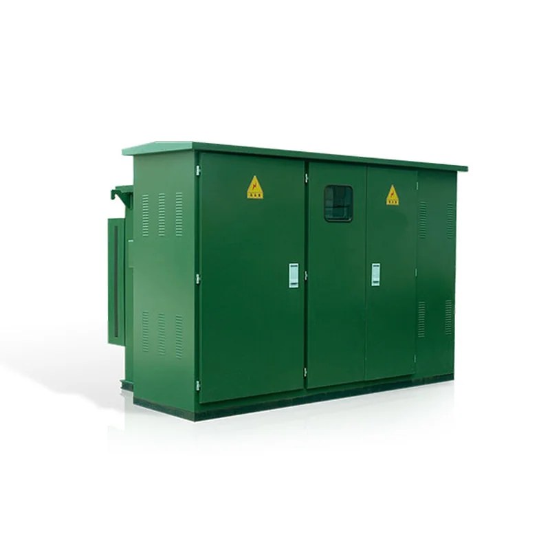
Product Overview
This product is developed by absorbing foreign technology and combining domestic practice; the whole product features small volume, easy installation and maintenance, low noise, low loss, anti-theft, strong overload capability and full protection. It is suitable for newly built quarters, green belts, parks, stations, hotels, construction sites, airports and other places. The ZGS-12 combined substation (American type) adopts a fully insulated, fully sealed structure, is nearly maintenance-free and ensures personal safety.
The ZGS□-12 combined substation (American type) is suitable for 10 kV ring-main supply, dual-power supply or terminal supply systems, serving as transformation, metering, compensation, control and protection equipment.
Type Designation

Features & Advantages
- Fully insulated, fully sealed, nearly maintenance-free, reliably ensuring personal safety;
- Compact structure, only 1/3-1/5 the volume of European-type substations of the same capacity, low height;
- Split-tank structure available to avoid oil contamination of the transformer tank;
- The HV side adopts double-fuse full-range protection, greatly reducing costs:
- Suitable for both ring-main and terminal use; cable connectors can be urgently plugged/unplugged at 200 A load current;
- The tank adopts honeycomb double-sandwich composite panels with heat insulation and heat dissipation;
- An electronic phase-failure protector is added on the LV side; when abnormal voltage appears in the system, the main incoming switch can be disconnected quickly;
- The HV side uses an oil-immersed load switch or SF6 load switch, upgradeable to motorized operation, laying a foundation for distribution automation.
- Oil-immersed S9 or better-performing S11 series transformers are used.
Service Conditions
- Altitude not exceeding 1000 m;
- Ambient temperature: -35℃ to +40℃;
- Relative humidity: daily average not exceeding 95%, monthly average not exceeding 90%;
- Installation site: free from fire, explosion hazards and chemically corrosive gases, well ventilated, with ground inclination not more than 3°.
Applicable Standards
GB/T 17467-1998 "High-voltage/low-voltage prefabricated substations"
DL/T 537-93 "Ordering technical conditions for 6-35 kV box-type substations"
Technical Parameters
Technical parameters of the combined substation
| No. | Item | Unit | Technical parameters |
|---|---|---|---|
| 1 | Rated voltage | kV | 10/0.4 (HV/LV) |
| 2 | Operating voltage | kV | 12 (HV side) |
| 3 | Rated frequency | Hz | 50 |
| 4 | Rated capacity | kVA | 150-1600 |
| 5 | 1-min power-frequency withstand voltage | kV | 35 |
| 6 | Lightning impulse voltage | kA | 75 |
| 7 | Cooling method | - | ONAN (oil-immersed self-cooled) |
| 8 | HV backup fuse breaking current | kA | 50 |
| 9 | Bayonet fuse breaking current | kA | 2.5 |
| 10 | Ambient temperature | ℃ | -35~+40 |
| 11 | Winding temperature rise | K | 65 |
| 12 | Off-circuit voltage regulation | - | ±5% or ±2×2.5% |
| 13 | Noise level | db | 50 |
| 14 | Protection class | - | IP43 |
Transformer
The new S9 series transformer body is selected, with low loss, good overload capability and strong short-circuit withstand; all fasteners are protection-treated. The S11 series wound seamless-core transformer with better performance is also available.
| Capacity (kVA) | Voltage (kV) | Connection group | No-load current (%) | No-load loss (W) | Impedance voltage% | Load loss (W) | |||||||
|---|---|---|---|---|---|---|---|---|---|---|---|---|---|
| HV | LV | S9 | S10 | S11 | S9 | S10 | S11 | S9 | S10 | S11 | |||
| 50 | 10±5% or ±2×2.5% |
0.4 | Dyn11 Yyno |
2.0 | 1.9 | 0.75 | 0.17 | 0.15 | 0.12 | 4.0 | 0.87 | 0.83 | 0.87 |
| 63 | 1.9 | 1.8 | 0.7 | 0.2 | 0.18 | 0.14 | 1.04 | 0.99 | 1.04 | ||||
| 80 | 1.9 | 1.7 | 0.7 | 0.25 | 0.22 | 0.175 | 1.25 | 1.2 | 1.25 | ||||
| 100 | 1.8 | 1.55 | 0.65 | 0.29 | 0.26 | 0.2 | 1.5 | 1.42 | 1.5 | ||||
| 125 | 1.7 | 1.45 | 0.65 | 0.34 | 0.3 | 0.235 | 1.8 | 1.72 | 1.8 | ||||
| 160 | 1.6 | 1.3 | 0.6 | 0.4 | 0.36 | 0.27 | 2.2 | 2.12 | 2.2 | ||||
| 200 | 1.5 | 1.2 | 0.55 | 0.48 | 0.43 | 0.33 | 2.6 | 2.5 | 2.6 | ||||
| 250 | 1.4 | 1.1 | 0.5 | 0.56 | 0.5 | 0.39 | 3.05 | 2.9 | 3.05 | ||||
| 315 | 1.4 | 1.0 | 0.45 | 0.67 | 0.29 | 0.465 | 3.65 | 3.45 | 3.65 | ||||
| 400 | 1.3 | 1.0 | 0.4 | 0.8 | 0.71 | 0.56 | 4.3 | 4.15 | 4.3 | ||||
| 500 | 1.2 | 1.0 | 0.4 | 0.96 | 0.85 | 0.67 | 4.5 | 5.15 | 4.82 | 5.15 | |||
| 630 | 1.1 | 0.8 | 0.4 | 1.2 | 1.6 | 0.81 | 6.2 | 5.86 | 6.2 | ||||
| 800 | 1.0 | 0.7 | 0.35 | 1.4 | 1.23 | 0.98 | 7.5 | 7.2 | 7.5 | ||||
| 1000 | 1.0 | 0.6 | 0.3 | 1.7 | 1.5 | 1.15 | 10.3 | 9.8 | 10.3 | ||||
| 1250 | 0.9 | 0.6 | 0.27 | 1.95 | 1.72 | 1.36 | 12.0 | 12.2 | 12.0 |
Load Switch
The load switch is oil-immersed, three-pole linked with a spring operating mechanism; it can make/break under load, with switching speed independent of the operating force; types available: two-position, four-position T type, four-position V type, etc.
Technical parameters
| Item | Item | Unit | 315A | 630A |
|---|---|---|---|---|
| Rated voltage | - | kV | 12 | 12 |
| Rated current | - | A | 315 | 630 |
| Rated frequency | - | Hz | 50 | 50 |
| Rated short-circuit making current | - | kA | 31.5 | 50 |
| Rated short-time withstand current | - | kA | 12.5 | 50 |
| Rated short-time duration | - | S | 2 | 2 |
| Mechanical endurance | - | operations | 2000 | 2000 |
| Lightning impulse test | Between phases & to earth | kV | 75 | 75 |
| Isolating gap | kV | 85 | 85 | |
| 1-min power-frequency withstand voltage | Between phases & to earth | kV | 42 | 42 |
| Isolating gap | kV | 48 | 48 | |
| Rated peak withstand current | - | kA | 31.5 | 50 |
Fuse
The HV side of the American box-type substation is provided with full-range protection by a backup protection fuse in series with a bayonet fuse — simple in principle, economical and reliable. The backup protection fuse is an oil-immersed HV current-limiting fuse with large breaking capacity, acting only on internal transformer faults; the bayonet fuse contains a dual-sensitive fuse link providing double protection of current and temperature, and after melting the fuse link can be conveniently replaced on site.
Technical parameters
| No. | Three-phase transformer capacity (kVA) | Transformer primary voltage (10 kV) | |
|---|---|---|---|
| - | - | XRNT rated current (A) | PRNT1 overload-protection rated current (A) |
| 1 | 30 | 10 | 6 |
| 2 | 50 | 16 | 8 |
| 3 | 80 | 16 | 10 |
| 4 | 100 | 20 | 15 |
| 5 | 125 | 25 | 15 |
| 6 | 160 | 31.5 | 25 |
| 7 | 200 | 40 | 25 |
| 8 | 250 | 50 | 40 |
| 9 | 315 | 63 | 40 |
| 10 | 400 | 63 | 40 |
| 11 | 500 | 80 | 50 |
| 12 | 630 | 100 | 50, 65 |
| 13 | 800 | 125 | 65 |
| 14 | 1250 | 160 | 100 |
| 15 | 1600 | 200 | 140 |
Substation Structure
The tank structure consists of three compartments: HV, LV and oil-tank compartments. The HV compartment includes HV cable accessories, the load switch, off-circuit tap changer, bayonet fuse, pressure release valve, oil level gauge, oil temperature gauge and oil drain valve. The LV compartment includes LV bushings, LV metering instruments, circuit breakers and capacitor compensation. The oil-tank compartment includes the transformer windings and core, radiator; the HV load switch and fuses are inside the oil tank. Per scheme requirements, the substation structure can be designed in a triangular or rectangular layout (see the figure below).

Operating Instructions
Operating the load switch:
The oil-immersed load switches used in the combined substation have three types according to their functions: two-position, four-position T type and four-position V type; one of them can be selected, and the operations of the three are as follows: the load switch of the ZGS-12 combined substation (American type) is available in two-position, four-position T type and four-position V types.
◇ For the four-position V-type load switch, see Figure 2; the moving blade is a "V"-shaped structure, shown in black in the figure; "Ⅰ, Ⅱ" in the figure are the ring-main supply incoming/outgoing lines, and "T" is the transformer HV incoming line via the backup fuse and bayonet fuse. The ring-main load switch switches the network under load.
The four operating positions of the load switch:
- ◇ At the "Ⅰ-Ⅱ-T" position, networks Ⅰ and Ⅱ are connected and the transformer is energized (the substation serves as a ring-main unit);
- ◇ At the "Ⅰ-T" position, network Ⅰ is connected to the transformer (the substation serves as a terminal);
- ◇ At the "Ⅱ-T" position, network Ⅱ is connected to the transformer (the substation serves as a terminal);
- ◇ At the "O" position, both networks Ⅰ/Ⅱ and the transformer are disconnected (nothing is live).
Insert the special operating handle into the switch shaft and rotate about 130° clockwise or counterclockwise; each operation advances the moving blade by one step. Switching example: changing supply from source "Ⅰ" to source "Ⅱ". The HV side of the ZGS-12 combined substation (American type) connects to the transformer HV incoming line via the backup fuse and bayonet fuse.
- ◇ Insert the special operating handle into the switch shaft;
- ◇ Turn the switch clockwise once; the "V"-shaped blade is now at the "Ⅰ-Ⅱ-T" position;
- ◇ Turn clockwise once more; the "V"-shaped blade is now between "Ⅱ-T", supplied by source "Ⅱ"; operation complete.
Operating method 2:
- ◇ Insert the special operating handle into the switch shaft;
- ◇ Turn the switch counterclockwise once; the "V"-shaped blade is now at the "O" position:
- ◇ Turn counterclockwise once more; the "V"-shaped blade is now between "Ⅱ-T", supplied by source "Ⅱ"; operation complete.
Both methods can switch the supply from source "Ⅰ" to "Ⅱ", but the second method is safer and more reasonable: after source "Ⅰ" is cut off it will not be re-energized, and if source "Ⅱ" fails the switch will not close onto the fault. With method 1, however, both sources may be connected simultaneously; when switching from source "Ⅰ" to "Ⅱ", faults may occur due to phase difference between the sources.
Appendix 1: Typical HV Schemes
| Scheme No. | H-01 | H-02 | H-03 |
|---|---|---|---|
| Main-circuit single-line diagram | 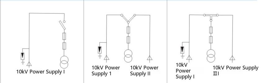 |
||
| - | Terminal-type American substation with a two-position load switch. | Ring-main-type American substation with a four-position "V"-type load switch. | Ring-main-type American substation with a four-position "T"-type load switch. |
| - | Single-source supply, suitable for terminal users | Ring-main or dual-power supply; however, when the transformer is disconnected, HV sources I and II are disconnected simultaneously; ring-main current 315 A, 630 A. | Ring-main or dual-power supply; when the transformer is disconnected, the two HV sources are not connected to each other; ring-main current 315 A, 630 A. |
| Scheme No. | H-04 | H-05 | - |
|---|---|---|---|
| Main-circuit single-line diagram | 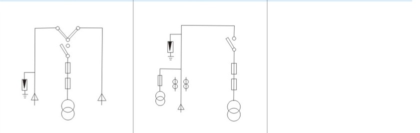 |
||
| - | Terminal-type American substation with a four-position "V"-type and two-position load switch. | Terminal-type American substation with HV metering function. | - |
| - | Ring-main or dual-power supply; a complete ring-main scheme; ring-main current 315 A, 630 A. | For users requiring HV metering | - |
Appendix 2: Typical LV Schemes
| Scheme No. | L-01 | L-02 | L-03 |
|---|---|---|---|
| Main-circuit single-line diagram | 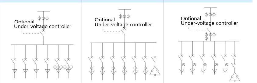 |
||
| American substation type | Terminal-type American substation with a two-position load switch. | Ring-main-type American substation with a four-position "V"-type load switch. | Ring-main-type American substation with a four-position "T"-type load switch. |
| Switch selection | Main switch, overall metering (active/reactive), active metering of two branch ways, outgoing 63-1250 A, optional undervoltage controller; for all capacities. | Main switch, overall metering (active/reactive), outgoing 63-1250 A, optional undervoltage controller; for all capacities. | Main switch, overall metering (active/reactive), outgoing 63-1250 A, reactive compensation 30-360 kvar, optional undervoltage controller; for all capacities. |
| Scheme No. | L-04 | L-05 | L-06 |
|---|---|---|---|
| Main-circuit single-line diagram | 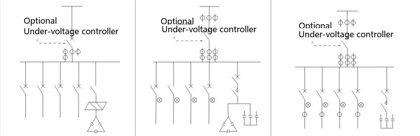 |
||
| American substation type | Terminal-type American substation with a two-position load switch. | Ring-main-type American substation with a four-position "V"-type load switch. | Ring-main-type American substation with a four-position "T"-type load switch. |
| Switch selection | Main switch, overall metering (active/reactive), outgoing 63-1250 A, optional undervoltage controller; switching devices adopt intelligent composite switches and capacitive contactless switches; for all capacities. | Main switch, overall metering (active/reactive), outgoing 63-1250 A, optional undervoltage controller; compensation is three-phase common and split-phase; for all capacities. | Main switch, overall metering (active/reactive), outgoing 63-1250 A, reactive compensation 30-360 kvar, optional undervoltage controller with split-phase compensation; for all capacities. |
Related Products
Box-type substations of the same series and other types available: