



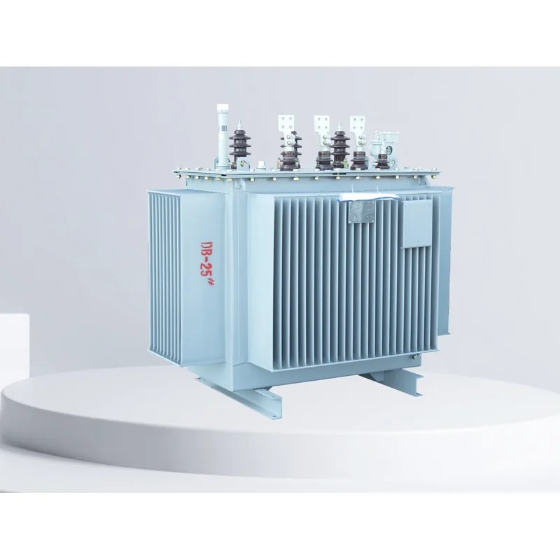
Overview
The three-phase oil-immersed distribution transformers manufactured by Gaosuo Electric Co., Ltd. adopt a new insulation structure in the core and winding, improving short-circuit withstand capability. High-quality oxygen-free copper wire is used as the conductor with a multi-layer cylindrical winding structure, and all fasteners receive special anti-loosening treatment. The products feature high efficiency and low loss, saving substantial power consumption and operating costs with significant social benefits. The core is made of high-quality cold-rolled silicon steel sheets, and the HV winding is a state-promoted high-tech product.
Type Designation
Reliable Structure
Based on the traditional structure and mature technology, Gaosuo Electric Co., Ltd. has made many improvements, such as: spiral windings with longitudinal oil ducts for better internal heat dissipation; improved effective support at the winding end faces for stronger short-circuit current withstand capability; and a new lifting structure and core/winding positioning structure ensuring higher reliability during long-distance transport and operation. Many other unique and reliable structures are provided for these oil-immersed distribution transformers; selecting a transformer of higher performance level yields a more advanced technical content.
Quality Materials
Oxygen-free copper wire with lower resistivity is selected and given a series of additional surface treatments, making it smoother without burrs or sharp corners, thereby lowering the load loss and improving electrical reliability. High-quality silicon steel sheets are selected; as the performance level rises, sheets with lower unit loss are adopted to reduce no-load loss. Quality laminated-wood insulation parts are selected that never crack, remaining stable even under short-circuit currents. Deep-filtered transformer oil with lower water, gas and impurity content is selected for more reliable operation. Quality rubber sealing materials are selected to effectively resist aging and prevent leakage. All raw materials pass quality inspection, and all suppliers are strictly audited in accordance with the national standard ISO9000.
Technical and Economic Performance
Compared with the S7 series, the S9 series reduces no-load loss, load loss and no-load current by 10%, 24% and 46% respectively, thereby lowering operating costs by 19%. Based on the S9 series, the S11 series reduces no-load loss by an average of 30%, no-load current by 70-85% compared with S9, and average temperature rise by 10K, more than doubling the product service life; it can operate long-term even under 20% overload, and operating noise is reduced by an average of 2-4 dB.
Fully Sealed Type (M)
In S11(M)R-, M indicates the tank adopts a fully sealed structure. Compared with ordinary oil-immersed distribution transformers, the fully sealed distribution transformer eliminates the conservator; the corrugated fins of the tank replace the oil pipes as cooling and heat-dissipating elements. The corrugated tank is manufactured from quality cold-rolled sheet on a dedicated production line, and the fins expand and contract with the volume change of the transformer oil, thereby isolating the transformer from the atmosphere, preventing and slowing oil deterioration and insulation moisture, and enhancing operation reliability with maintenance-free normal operation. The corrugated tank surface is degreased, derusted and phosphated, then coated with three-proof paint, suitable for metallurgy, petrochemical, mining and similar environments.
- Code for special service environment (GY-plateau, WF-anti-corrosion, TA-dry tropical, TH-warm tropical)
- Voltage level (kV)
- Rated capacity (kVA)
- Code for special purpose or structure (M-fully sealed, R-wound core)
- Performance level code (9, 10, 11, 12)
- Product type letters (D-single-phase, S-three-phase, F-forced air cooling, Z-on-load tap changing)
Wound Core Type (R)
In S11(M)R-, R indicates the core adopts a wound core, using quality low-loss cold-rolled silicon steel sheets without punching or perforation, eliminating the transverse and longitudinal joints of the traditional core. This yields lower no-load current and lower reactive power loss of the transformer, and a lower noise level, making the transformer more environmentally friendly. With an integral core, the clamp mainly clamps the windings, further strengthening the winding's short-circuit current withstand capability. The S11 series covers rated capacities from 30 kVA to 6300 kVA at a rated voltage of 10 kV and a rated frequency of 50 Hz.
Normal Service Conditions
Altitude not exceeding 1000m: Ambient temperature: maximum +40°C; hottest monthly average +30°C; highest annual average +20°C; outdoor minimum -25°C.
Special Service Conditions
Altitude exceeding 1000m
Ambient temperature: maximum +40°C; minimum -45°C.
Please specify in detail when ordering.
S11 Series 10kV Distribution Transformer
30kVA~2500kVA Three-phase Double-winding Non-excitation Regulating Distribution Transformer
| Rated capacity (kVA) | Voltage combination and tapping range | Vector group | Losses (kW) | No-load current (%) | Short-circuit impedance (%) | Weight (kg) | Outline dimensions (mm) L×W×H | Wheel track longitudinal/transverse (mm) | ||||||
|---|---|---|---|---|---|---|---|---|---|---|---|---|---|---|
| HV (kV) | HV tapping range (%) | LV (kV) | No-load | Load | Core & winding | Oil | Total | Sealed | Non-sealed | |||||
| 30 | 66.31010.511 | ±5±2×2.5 | 0.4 | Dyn11Yzn11Yyn0 | 0.10 | 0.63/0.60 | 2.3 | 4.0 | 150 | 750 | 340 | 730×780×930 | 950×720×1000 | 400/400 |
| 50 | 0.13 | 0.91/0.87 | 2.0 | 220 | 950 | 440 | 800×750×965 | 1020×700×1035 | 400/400 | |||||
| 63 | 0.15 | 1.09/1.04 | 1.9 | 260 | 110 | 490 | 820×780×970 | 1140×740×1040 | 400/400 | |||||
| 80 | 0.18 | 1.31/1.25 | 1.9 | 300 | 120 | 580 | 840×800×1000 | 1060×720×1070 | 400/400 | |||||
| 100 | 0.20 | 1.58/1.50 | 1.8 | 350 | 120 | 660 | 850×840×1010 | 1105×760×1110 | 450/400 | |||||
| 125 | 0.24 | 1.89/1.80 | 1.7 | 400 | 130 | 700 | 860×900×1080 | 1120×800×1150 | 550/550 | |||||
| 160 | 0.27 | 2.31/2.20 | 1.6 | 480 | 160 | 840 | 1220×840×1100 | 1440×760×1290 | 550/550 | |||||
| 200 | 0.34 | 2.73/2.60 | 1.5 | 560 | 170 | 920 | 1250×860×1150 | 1470×780×1350 | 550/550 | |||||
| 250 | 0.40 | 3.20/3.05 | 1.4 | 640 | 180 | 1040 | 1260×850×1220 | 1480×780×1420 | 550/550 | |||||
| 315 | 0.48 | 3.83/365 | 1.4 | 800 | 200 | 1220 | 1340×900×1200 | 1560×840×1400 | 550/550 | |||||
| 400 | 0.57 | 4.52/4.30 | 1.3 | 980 | 240 | 1460 | 1380×900×1260 | 1600×840×1520 | 550/550 | |||||
| 500 | 0.68 | 5.41/5.15 | 1.2 | 1130 | 280 | 1710 | 1520×1000×1330 | 1740×960×1590 | 660/660 | |||||
| 630 | Dyn11Yyn0 | 0.81 | 6.20 | 1.1 | 4.5 | 1350 | 330 | 2050 | 1580×1040×1270 | 1900×1040×1600 | 660/660 | |||
| 800 | 0.98 | 7.50 | 1.0 | 1610 | 400 | 2460 | 1650×1160×1400 | 1970×1160×1730 | 820/820 | |||||
| 1000 | 1.15 | 10.30 | 1.0 | 1690 | 450 | 3680 | 1750×1240×1460 | 2070×1240×1970 | 820/820 | |||||
| 1250 | 1.36 | 12.00 | 0.9 | 1910 | 500 | 3050 | 1800×1240×1550 | 2100×1240×1870 | 820/820 | |||||
| 1600 | 1.64 | 14.50 | 0.8 | 2330 | 590 | 3800 | 1830×1800×1930 | 1830×1800×1930 | 820/820 | |||||
| 2000 | 2.05 | 17.50 | 0.6 | 2750 | 780 | 4660 | 1950×1900×2080 | 1950×1900×2080 | 820/820 | |||||
| 2500 | 2.50 | 21.00 | 0.6 | 3350 | 920 | 5440 | 2060×1930×2130 | 2160×1930×2130 | 1070/1070 | |||||
Outline Dimensions
S11 Series 10kV Distribution Transformer (630kVA~6300kVA, Yd11)
| Rated capacity (kVA) | Voltage combination and tapping range | Vector group | Losses (kW) | No-load (%) | Short-circuit impedance | Weight (kg) | Wheel track long./trans. | |||||
|---|---|---|---|---|---|---|---|---|---|---|---|---|
| HV (kV) | HV tapping range (%) | LV (kV) | No-load | Load | Core & winding | Oil | Total | |||||
| 630 | 66.31010.511 | ±5±2X2.5 | 33.156.3 | Yd11 | 0.84 | 1780 | 450 | 2710 | 750/660 | |||
| 800 | 1.02 | 8.46 | 2100 | 520 | 3310 | 850/660 | ||||||
| 1000 | 1.20 | 2580 | 3860 | 850/820 | ||||||||
| 1250 | 1.42 | 11.80 | 2880 | 700 | 4370 | 850/820 | ||||||
| 1600 | 1.71 | 14.11 | 3400 | 4760 | 900/820 | |||||||
| 2000 | 2.04 | 16.93 | 3800 | 5570 | 900/820 | |||||||
| 2500 | 2.40 | 19.67 | 4350 | 960 | 6670 | 1070/1070 | ||||||
| 3150 | 2.84 | 23.09 | 4940 | 1180 | 8500 | 1070/1070 | ||||||
| 4000 | 1010.511 | 3.156.3 | 3.48 | 27.36 | 0.7 | 5900 | 1580 | 9850 | 1070/1070 | |||
| 5000 | 4.16 | 31.38 | 6850 | 1760 | 11580 | 1070/1070 | ||||||
| 6300 | 35.06 | 7920 | 1910 | 13650 | 1070/1070 | |||||||
S11 Series 10kV On-load Tap-changer Distribution Transformer (200kVA~2500kVA)
| Rated capacity (kVA) | Voltage combination and tapping range | Vector group | Losses (kW) | No-load current (%) | Short-circuit impedance (%) | Weight (kg) | Wheel track longitudinal/transverse (mm) | |||||
|---|---|---|---|---|---|---|---|---|---|---|---|---|
| HV (kV) | HV tapping range (%) | LV (kV) | No-load | Load | Core & winding | Oil | Total | |||||
| 200 | 66.310 | ±4×2.5 | 0.4 | Dyn11Yyn0 | 0.39 | 2.91 | 1.5 | 4.04.5 | 980 | 260 | 1530 | 550/550 |
| 250 | 0.45 | 3.42 | 1.4 | 1070 | 310 | 1740 | 650/550 | |||||
| 315 | 0.54 | 4.10 | 1.4 | 1320 | 350 | 1980 | 650/550 | |||||
| 400 | 0.65 | 4.96 | 1.3 | 1580 | 430 | 2270 | 750/550 | |||||
| 500 | 0.77 | 5.90 | 1.2 | 1750 | 450 | 2500 | 750/660 | |||||
| 630 | 0.97 | 7.27 | 1.1 | 1900 | 530 | 2920 | 750/660 | |||||
| 800 | 1.13 | 8.89 | 1.0 | 2150 | 600 | 3320 | 850/660 | |||||
| 1000 | 1.38 | 10.43 | 1.0 | 2480 | 680 | 3710 | 850/820 | |||||
| 1250 | 1.58 | 12.40 | 0.9 | 2620 | 770 | 4200 | 850/820 | |||||
| 1600 | 1.94 | 14.79 | 0.8 | 3100 | 880 | 4850 | 900/820 | |||||
| 2000 | 2.27 | 18.69 | 0.6 | 3980 | 1080 | 5880 | 900/820 | |||||
| 2500 | 2.52 | 21.74 | 0.6 | 3950 | 1300 | 6370 | 1070/1070 | |||||


Related Products
Transformers of the same series and other types available for selection: